
User Manual

Delta 1-24 LSC&
Delta 2-24 LSC&
2 Layout and mode of operation
14
Version 04/2013, Rev. 1.2 of 20/02/2014 • sb
Translation of the original operating manual
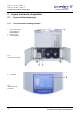
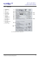
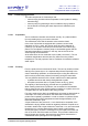
11 Aeration valve
12 Media drain valve
13 Fixed castors
Fig. 5: Left side of the
freeze-dryer
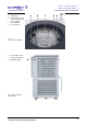
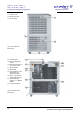
14 Vacuum sensor
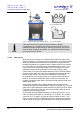
15 Mains voltage (Main
switch)
16 Electrical connection of
the vacuum sensor
17 Serial interface
18 Mains cable
19 Heat exchanger of the
refrigeration unit
(behind the panel)
20 Option: Connection for
electrical lifting device
21 Name plate (see
chapter 2.1.2 - "Name
plate")
22 Vacuum connection
Fig. 6: Rear side of the
freeze-dryer
Pos: 20 /010 Unive rsalm odule/ Seit enwec hsel @ 0\m od_120 2116244 312_0. docx @ 105 @ @ 1