
User guide

Beta 1-8 LSC&
Beta 2-8 LSC&
11 Appendix
Version 04/2013, Rev. 1.1 of 16/12/2013 • sb
93
Translation of the original operating manual
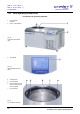
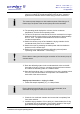
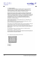
8 Mains power switch
Fig. 78: Right side of the
freeze-dryer
9 Aeration valve
10 Media drain valve
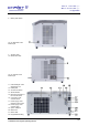
Fig. 79: Left side of the
freeze-dryer
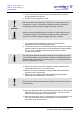
11 Heat exchanger of the
refrigeration unit
12 Name plate
13 Vacuum connection
14 Serial interface
15 Electrical connection of
the vacuum sensor
16 Connection of the
vacuum sensor
17 Power supply of the
pressure control valve
18 Power supply of the
vacuum pump
19 Option: USB port
20 Mains fuse
21 Mains cable
22 Equipotential bonding