
User guide

Beta 1-8 LSC&
Beta 2-8 LSC&
5 Set-up and connection
34
Version 04/2013, Rev. 1.1 of 16/12/2013 • sb
Translation of the original operating manual
NOTE
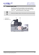
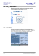
The vacuum sensor comes supplied in a calibrated state.
After the freeze-dryer has been switched on, the vacuum sensor needs
several minutes until it is ready for operation.
Pos: 104 /01 0 Univ ersal module/ Sei tenwe chsel @ 0\ mod_12 0211624 4312_0 .docx @ 105 @ @ 1
Pos: 105 /20 0 Ch rist/3 61 G T-BA Labo r-P ilot (PR OJEK TE)/B et a 1-8_ 2-8 LSCpl us/ 050 Au fstel lu ng u nd Ans chlus s/ 050 -0060 V akuu mpu mp e Beta @ 16 \mo d_1359 106 6219 62_ 68. docx @ 80 814 @ 2 @ 1
5.4.6 Vakuum pum pe
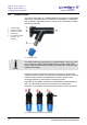
5.6 Vacuum pump
NOTE
Please refer to the separate operating manual of the vacuum pump and
the exhaust filter!
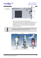
The vacuum pump must be connected to the vacuum connector of the unit
and its plug must be plugged into the IEC C14 connector on the back of the
unit (see chapter 2.1.1 - "Functional and operating elements").
The oil mist that escapes when the pump is in operation must be retained
or carried off by way of an oil mist separator.
• We strongly recommend using an oil mist separator. This filter prevents
air pollution by oil mist.
• In order to carry off the oil mist, connect a suitable hose to the exhaust
port of the vacuum pump (RZ-2.5 and RC-6: ½", DUO 5 or DUO 10 ¾").
• The hose must be laid so that the condensate cannot flow back into the
pump. In the case of upward leading hoses, we recommend using a
separator (Woulfe's bottle or wash bottle).
Pos: 106 /01 0 Univ ersal module/ Lee rzeile @ 0\ mo d_12021 162445 00_ 0.docx @ 1 14 @ @ 1
Pos: 107 /20 0 Ch rist/3 61 G T-BA L abo r-Pil ot (P ROJE KTE )/Bet a 1 -8_2-8 LSC plus/ 050 Au fstel lu ng und A ns chluss / 050-00 70 D rucks teu erve ntil B eta @ 1 6\m od_1 359 106 622184 _68. docx @ 80 822 @ 2 @ 1