
User guide

Beta 1-8 LSC&
Beta 2-8 LSC&
5 Set-up and connection
32
Version 04/2013, Rev. 1.1 of 16/12/2013 • sb
Translation of the original operating manual
Pos: 98 / 200 Chris t /36 1 GT-B A La bor -Pil ot (PROJ EK TE )/Beta 1- 8_2 -8 LSCpl us /0 50 Aufs tel lun g un d Ansc hlus s/0 50- 003 0 Belü ftun gsven ti l Beta @ 16\ mo d_1 3591 066 209 93_68. doc x @ 80798 @ 2 @ 1
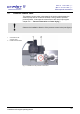
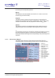
5.3 Aeration valve
The aeration valve is located on top of the left side of the unit (see chapter
2.1.1 - "Functional and operating elements").
After the end of a freeze-drying process, the unit will be aerated via the
aeration valve.
NOTE
The ice condenser chamber can be flooded with nitrogen via the hose
nozzle of the aeration valve.
WARNING
For the aeration with gases under pressure, the client must install a safety
device for pressure relief.
Pos: 99 /010 Unive rsalm odule/ L ee rzeile @ 0\ mod _120211 624450 0_0.docx @ 11 4 @ @ 1
Pos: 100 /01 0 Univ ersal module/ Lee rzeile @ 0\ mo d_12021 162445 00_ 0.docx @ 1 14 @ @ 1
Pos: 101 /20 0 Chri st/3 61 GT-BA Labo r-Pi lot (PROJE KTE )/Bet a 1-8_ 2-8 LSCplus /050 A uf stellu ng u nd Ans chluss /050 -00 40 Me diena blauf ventil B e ta @ 16\ mod _13591 066 212 57_68. docx @ 808 06 @ 2 @ 1
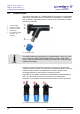
5.4 Media drain valve
The media drain valve is located at the bottom of the left side of the unit
(see chapter 2.1.1 - "Functional and operating elements").
It is used to drain off the condensate and the defrosting water.
• Connect the drain hose (included in the scope of supply) to the hose
connector.
• Place a collecting vessel under the unit.
The hose must be laid with a continuous slope and the end of the hose
must always be above the liquid level in the collecting vessel. This prevents
water and dirt residues from being sucked into the ice condenser chamber
if there is negative pressure when the media drain valve is opened.
Pos: 102 /01 0 Univ ersal module/ Lee rzeile @ 0\ mo d_12021 162445 00_ 0.docx @ 1 14 @ @ 1
Pos: 103 /20 0 Ch rist /3 61 GT-B A L abo r-Pil ot (P ROJE KTE )/Bet a 1 -8_ 2-8 LS Cplus / 050 Au fstel lu ng u nd Ans chlus s/ 050 -0050 V a kuu mmes sson de Bet a @ 16\m od_ 135 910 662034 8_68 .docx @ 8 079 0 @ 2 @ 1
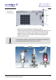
5.5 Vacuum sensor
NOTE
Please refer to the separate operating manual of the vacuum sensor!
In order to protect the vacuum sensor against transport damage, it comes
supplied in its original packaging. Prior to commissioning the freeze-dryer,
the sensor must be installed.