
User guide

Beta 1-8 LSC&
Beta 2-8 LSC&
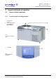
2 Layout and mode of operation
12
Version 04/2013, Rev. 1.1 of 16/12/2013 • sb
Translation of the original operating manual
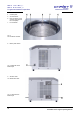
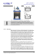
4 Contact piece
5 Vacuum sensor
6 Pipe connection of the
vacuum pump (behind
the cover plate)
7 Ice condenser
Fig. 3:
Ice condenser chamber
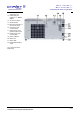
8 Mains power switch
Fig. 4: Right side of the
freeze-dryer
9 Aeration valve
10 Media drain valve
Fig. 5: Left side of the
freeze-dryer