
Owner's manual

ALPHA 1-4 LSC&
ALPHA 2-4 LSC&
2 Layout and mode of operation
Version 01/2011, Rev. 1.5 of 16/12/2013 • sb
11
Translation of the original operating manual
Pos: 17 / 200 Chri st /36 0 GT -BA La bor -Pi lot (S TA NDA RDMOD ULE )/ 020 A ufb au u nd Wirk ungs w eise/ 020 Auf bau u nd W ir kung swei se == ===== == ===== == ===== == ==== @ 5\m od_ 129 913 628 8294_68 .doc x @ 3 4555 @ 1 @ 1
2 Layout and mode of operation
Pos: 18 / 200 C hrist /36 0 GT -BA La bor -Pil ot (S TAN DA RDMOD ULE) /02 0 A ufb au u nd Wirk ungs wei se/ 020 -00 10 Au fba u de r Ge frie rtr ock nu ngsa nlag e-- ----- --- ----- -- --- ----- --- ----- --- ----- -- ----- - @ 5 \mo d_1 299 1362 888 09_ 68. docx @ 345 63 @ 2 @ 1
2.1 Layout of the freeze-dryer
Pos: 19 / 200 Christ /36 1 GT -BA La bor-P ilot (P ROJE KTE )/A lpha 1- 4_2-4 LS C plus/0 20 A uf bau und Wi rku ngsweis e/02 0-0 010 -00 10 Fu nktio ns- u nd Be di enel em ente @ 5\ mod _12 979 383 54859_ 68.d ocx @ 324 71 @ 3 @ 1
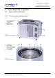
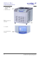
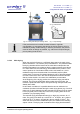
2.1.1 Functional and operating elements
1 Ice condenser chamber
with an internal ice
condenser
2 Aeration valve
3 Media drain valve
Fig. 1:
Left side of the freeze-dryer
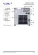
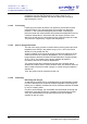
4 Contact piece
5 Vacuum sensor
6 Pipe connection of the
vacuum pump (behind
the cover plate)
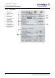
7 Ice condenser
Fig. 2:
Ice condenser chamber