
Instruction Manual


Freeze-dryer Alpha 1-2 LDplus
2 Layout and mode of operation
Version 11/2006, Rev. 2.0 of 02/12/2014 • sb
13
Translation of the original operating manual
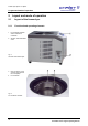
5 User interface (see
chapter 6.5.1 - "User
interface")
6 Mains power switch
Fig. 3:
Front and right side of the
freeze-dryer
7 Name plate (see chapter
2.1.2 - "Name plate")
8 Power supply of the
pressure control valve
9 Power supply of the
vacuum pump
10 Equipotential bonding
screw
11 Mains connection
12 Vacuum connection
13 Connection of the
vacuum sensor
14 Option: data interface for
further accessories
15 Heat exchanger of the
refrigeration unit
Fig. 4:
Rear view of the freeze-dryer
Pos: 20 / 010 U nive rsalm odul e/S eite nwechs el @ 0 \mo d_1 202116 244 312_ 0.d ocx @ 105 @ @ 1