
User`s guide


Q Series Operation Manual 15
The headroom available through the input stage to
the clip limiter is shown by the dotted lines as +10
dB at 141 Vpeak and +20.4 dB at 42 Vpeak. These
lines illustrate the additional signal level that can be
accepted at the input before any significant distortion
will appear at the input stage.
If you use the level potentiometer in the
signal chain to reduce the level by an amount
greater than the headroom relative to input
sensitivity, AND you drive the amplifier to
clip level, you are in danger of clipping the input stage
before the current or voltage peak limiters are
activated.
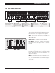
7.3.2 Headroom, sensitivity and VPL / Gain
settings
The input amplifier and limiter system is designed to
accommodate extremes of performance. Typically,
exceeding maximum input by much as +10 dB will
only result in a 1% increase in distortion. The
following schematics illustrate how the adjusable
VPL and Gain circuitry affect input sensitivity and
output power:
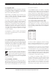
The tables to the left of the drawing below, show
input sensitivity for MA6.8Q with an 8 ohm load and
141 Vpeak (max.) and 42 Vpeak (min.) respectively
for the eightdifferent gain stages between +23 dB
and +44 dB. The resulting output power is displayed
in dBu, Vrms and Watt in the tables to the far right.
Complete input sensitivity tables for all VPL and
Gain settings for all Q Series models, can be found
at www.martin-audio.com.
The headroom available through the input stage to
the clip limiter is shown by the dotted lines as +10
dB at 141 Vpeak and +20.4 dB at 42 Vpeak. These
lines illustrate the additional signal level that can be
accepted at the input before any significant distortion
will appear at the input stage.
Gai
n
set to:
(DIP-switches)
+ 44
dB
+ 41
dB
+ 38
dB
+ 35
dB
+ 32
dB
+ 29
dB
+ 26
dB
+ 23
dB
Voltage Peak
Limiter set to:
(DIP-switches)
141 V
peak
11
8 V
peak
100 V
peak
85 V
peak
71 V
peak
59 V
peak
50 V
peak
42
V
peak
Input
se
n
sitiv
ity
dBu / V
rms
-2,0 /
0,6
1,0 / 0,9
4,0 / 1,2
7,0 / 1,7
10,0 / 2,5
13,0 / 3,5
16
,
0 / 4,9
19
,
0 / 6,9
Gain
set to:
(DIP-
switches)
+ 44
d
B
+ 41 d
B
+ 38
d
B
+ 35
d
B
+ 32
d
B
+ 29 d
B
+ 26
d
B
+ 23
d
B
Input
sensi
tivity
dBu / V
rms
-12,3 / 0,2
-9,3 /
0,3
-6,
3 /
0,4
-3,3 /
0,5
-0,3 /
0,7
2,7 / 1,1
5,7 / 1,5
8,7 / 2,1
V
PL s
e
t to 42
V
pe
ak
VPL set to 141 V
peak
*
)
H
e
a
d
ro
m limited to +8d
B at Gain set
to +23 dB at Ma
x. VPL
Complete tables for all VPL
settings can be
found at:
www.martin-audio.com.
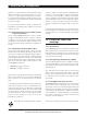
Hard/Soft switch
Gain
se
lect
s
w
i
t
ches
Front panel
p
o
te
nti
o
mete
r
Dy
namic
Ga
in red
uction
VPL se
lect
switches
Class T
D
Volta
ge
Cli
p sens
ing
Cur
re
n
t c
lip
se
nsing
Mon
i
to
ring
Level
Te
m
p
e
rature
Fault/
W
ar
n
ing
Co
nt
rol Mu
te
Input Amplifier
Level control
Clip Limiter
Voltage Peak Limiter
Output Power Amplifier
Output
power
dBu / V
rms
42,2 / 100
4
0,
7 / 84
3
9,2 / 71
3
7,8 / 60
3
6
,2 / 50
3
4,
7 / 42
3
3,1 / 35
3
1
,
8 / 30
Output
power
Watt
1200 W
880 W
6
30 W
440 W
310 W
220 W
1
60 W
110 W
+10 dB headr
oom to clip,
relati
ve
to input sensitivity
*)
+20,4 dB headroom to cl
ip,
relative to input sensitivity *)
OPERATION AND PERFORMANCE 7
All material © 2007. Martin Audio Ltd. Subject to change without notice.