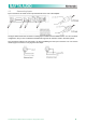
MA3.0 High Performance Amplifier User Guide The Martin Experience All material © 2010. Martin Audio Ltd. Subject to change without notice.
Contents Warning notices ............................................................................................ 3 1 Installation and operation ....................................................................... 6 1.1 1.2 1.3 1.4 1.5 1.6 2 Setup and settings ................................................................................ 10 2.1 2.2 3 Introduction ............................................................................................ 10 The LED indicators .................
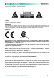
Important safety instructions Caution To reduce the risk of electric shock, do not remove the cover. No user-serviceable parts inside. Refer servicing to qualified service personnel. Safeguards Electrical energy can perform many useful functions. This unit has been engineered and manufactured to assure your personal safety. Improper use can result in potential electrical shock or fire hazards.
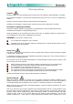
Warning notices Location Install the amplifier in a well-ventilated location where it will not be exposed to high temperature or humidity. Do not install the amplifier in a location that is exposed to direct rays of the sun, or near to hot appliances or radiators. Excessive heat can adversely affect the cabinet and internal components. Installation of the amplifier in a damp or dusty environment may result in malfunction or accident.
diaphragm is striking the magnet assembly. Martin Audio recommends that you use amplifiers of this power range for more headroom (cleaner sound) rather than for increased volume. Speaker output shock hazard A Martin Audio amplifier is capable of producing hazardous output voltages. To avoid electrical shock, do not touch any exposed speaker wiring while the amplifier is operating. This manual contains important information on operating your Martin Audio amplifier correctly and safety.
Introduction The totally new Martin Audio MA3.0 amplifier technology has changed the way the world looks at professional audio amplification. No other amplifiers come close for applications demanding high power and long term reliability. Thanks to amazing reductions in heat output along with reductions in weight and the specific high output power, MA3.
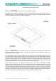
1 1.1 Installation and operation Unpacking Carefully open the shipping carton and check for any noticeable damage. Every Martin Audio amplifier is completely tested and inspected before leaving the factory and should arrive in perfect condition. If you find any damage, notify the shipping company immediately. Be sure to save the carton and all packing materials for the carrier's inspection. 1.2 Mounting The MA3.0 amplifiers will mount in a standard 19" rack.
1.3 Operating Precautions Make sure the AC mains voltage is correct and is the same as that printed on the rear of the amplifier. Damage caused by connecting the amplifier to improper AC voltage is not covered by the warranty. Make sure the power switch is off before making any input or output connections. It is always a good idea to have the gain controls muted during power-up to prevent speaker damage particularly if there is a high signal level at the inputs.
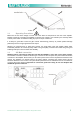
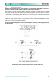
1.5 Connecting Inputs Input connections are made via the 3-pin XLR-female on the rear of the amplifier. The figure below shows the connection of analog input for balanced and unbalanced line. You can use either configuration, but you must consider that unbalanced long lines can introduce noise in the audio system. The Link switch located in the rear panel is for direct paralleling the rear input connectors. You can use the remaining input connector to carry signal to other amps.
1.6 Connecting Outputs Warning: there are lethal voltages at the loudspeaker connectors when the amplifier is turned on. To prevent any damages turn the amplifier off before connecting the loudspeaker. Output connectors are made via Neutrik Speakon connectors. Consult the wire gauge chart to find a suitable wire gauge to minimize power and damping factor losses in the speaker cables. The outputs can also work in bridge mode.
2 2.1 Setup and settings Introduction The figure right shows the front panel of the MA3.0 Amplifier. The front panel controls and indicators give the user total control and detailed information about the status of the amplifier. The gain control uses a logarithmic scale from -∞ to +32dB. Read the instructions below carefully which will explain the many functions of the amplifier. All material © 2010 Martin Audio Ltd.
2.2 The LED indicators The figure below shows the front panel of the MA3.0. The clip LED, when lighting, indicates the clipping state for the output stage of the corresponding channel. The signal, -18dB and -6dB LEDs operate as V-meter and the signal LED is illuminated when the signal is present in the input stage of the correspondent channel. The "ready" LED, when illuminated, indicates that the start-up time after power-on is finished and the amplifier is ready to use.
3 3.1 Protection Turn-On-Turn-Off muting For about four seconds after turn-on, and immediately at turn-off, the amplifier outputs are muted. 3.2 Short circuit protection A short circuit protection system safeguards the amplifier's output transistors under short circuits and other stressful loads. It is completely inaudible when inactive. In the event of a short circuit condition, the red LED will be illuminated.
4 4.1 User Maintenance Cleaning Disconnect the amplifier from the AC main source first; use a soft cloth and mild non-abrasive solution to clean the faceplate and chassis. 4.2 Service There are no user-serviceable parts in your MA3.0 amplifier. Refer servicing to qualified technical personnel. If your MA3.0 amplifier needs repair, contact your Martin Audio dealer or distributor. 4.
5 Warranty Martin Audio MA3.0 is warranted against manufacturing defects in materials or craftsmanship over a period of 3 (three) years from the date of original purchase. During the warranty period Martin Audio will, at its discretion, either repair or replace products which prove to be defective provided that the product is returned in its original packaging, shipping prepaid, to an authorised Martin Audio service agent or distributor. Martin Audio Ltd.
7 7.1 Technical notes Block diagram The diagram below shows the amplifier block diagram (1 Channel shown). All material © 2010 Martin Audio Ltd.
7.2 Thermal Dissipation Martin Audio MA3.0 Level Load Rated Power Switch in off position* Power on, amplifier in idle mode Pink Noise (1/8 rated power) Pink Noise (1/4 rated power) 8Ω / Stereo 16Ω / bridged 4Ω / stereo 8Ω / bridged 2Ω / stereo 4Ω / bridged Watt 2 x 900 1 x 1800 2 x 1500 1 x 3000 N/A N/A 8Ω / Stereo 16Ω / bridged 4Ω / stereo 8Ω / bridged 2Ω / stereo 4Ω / bridged 2 x 900 1 x 1800 2 x 1500 1 x 3000 N/A N/A AC Mains 230V AC 115V AC 0.13 0.2 0.09 0.
7.3 Specification POWER REQUIREMENTS Power supply....................................................................................115-230V (-15%, +15%) (50/60Hz) 800VA Operating temperature ................................................................................................................... 0°C to 45°C Weight....................................................................................................................................... 7.3Kg (16.
7.4 Technical Drawing All material © 2010 Martin Audio Ltd.