MA-NET1 & MA Netcontrol User’s Guide The Martin Experience All material © 2007. Martin Audio Ltd. Subject to change without notice.
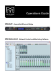
Operations Guide- MA-Net1 - Nomadlink/Ethernet Bridge MA Netcontrol - Network Control and Monitoring Software
Contents 1 2 Warnings Introduction 5 2.1 5 6 6 7 2.2 3 4 Installing the MA Netcontrol Application 7 7 8 8 8 Computer system requirements Software installation Software updates Uninstalling MA Netcontrol Connecting your PC to NomadLink 4.2 4.3 4.4 4.5 4.6 8 Determining preferred connection type 4.1.1 Peer-to-peer connection 4.1.2 LAN connection (wired or wireless) Establishing a peer-to-peer connection 4.2.
6.5 6.6 6.7 6.8 6.9 6.4.4 Matching to the physical subnet 6.4.5 Device Sorting Channels View 6.5.1 Overview 6.5.2 Forming Channel Groups Group View 6.6.1 Overview 6.6.2 Group View buttons and functions 6.6.3 Group View fault and warning indicators 6.6.4 Channel faults and warnings 6.6.5 Group and Subnet warning and fault icons 6.6.6 Level meters and clip LEDs Details View 6.7.1 Overview 6.7.2 Subnet details 6.7.3 Device details Tree View 6.8.1 Overview 6.8.2 Functionality Locking Functions 6.9.
1 Warnings The lightning symbol within a triangle is intended to alert the user to the presence of un-insulated “dangerous voltage” within the amplifier’s enclosure that may be of sufficient magnitude to constitute a risk of electric shock to humans. The exclamation point within a triangle is intended to alert the user to presence of important operating and service instructions in the literature accompanying the product.
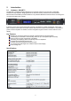
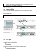
2 Introduction 2.1 Hardware - MA-NET1 The MA-NET1 NomadLink/Ethernet Bridge acts as a subnet master for up to 60 units of networked NomadLink-ready amplifiers. Bridging between the NomadLink daisy-chained network and standard Ethernet/LAN, the MA-NET1 provides utilization of any standard Ethernet architecture when connecting a PC running the MA Netcontrol software.
Rear panel detail 2.1.1 Mains connection To reduce the risk of fire or electrical shock, do not expose this apparatus to rain or moisture and objectfilled with liquids such as vases, should not be placed on the apparatus. This apparatus must be earthed. Use a three wire grounding type line cord like the one supplied with the product. Be advised that different operating voltages require the use of different types of line cord and attachment plugs. Check the voltage in your area and use the correct type.
This equipment generates, uses, and can radiate radio frequency energy and, if not installed and used in accordance with the instructions, may cause harmful interference to radio communications. However, there is no guarantee that interference will not occur in a particular installation.
3.2 Software installation Install the application by running the MA Netcontrol_Installer-1.2.0.exe (or later) installer. Follow the instructions as shown in the installation wizard. The application installs all necessary components needed to run MA Netcontrol. A shortcut for quick access to MA Netcontrol will be placed on your desktop. 3.
Note: A separate, third-party network device must be accommodated in the system to create a LAN connection. This could raise reliability issues, particularly in touring applications. Any network devices should be chosen with this consideration in mind. 4.2 Establishing a peer-to-peer connection 4.2.1 Physical connection You must first establish a NomadLink subnet before connecting your MA Netcontrol host computer. Connect the PC to the MA-NET1 unit using an Ethernet cable.
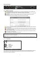
To establish a connection, use the following procedure: 1. In XP Home - Go to the START menu in the lower left corner, select “Connect to” and then “Show all connections” In XP Professional - Go to the START menu in the left corner, select “Settings”, “Control Panel” and then (if in classic view) “Network Connections”. If the “Control Panel” is in “Category view” choose “Network and Internet Connections” and then “Network Connections”. (Fig 2). 2. Select “Local Area Connection”.
4.4 Establishing a wired or wireless LAN connection It is recommended that you make your LAN connections using a network device (hub, switch or router) that includes a DHCP server function. This feature greatly simplifies network configuration. (For use with nonDHCP devices, see 4.5) Connect the host computer and one or more MA-NET1’s Bridges to the network device using standard Ethernet cables. To obtain an IP address automatically, each MA-NET1 must be set to “DHCP On”.
This window allows selection of an amplifier con-figuration for loading into MA Netcontrol. The choices are: Uploading information from connected subnet(s) Opening an already saved preset configuration file Creating a new configuration from scratch. If you are working offline (no physical subnet is connected), select the second or third choice to access offline editing functions. See Section 6.4.3.
If you are certain that subnets have been connected, this could indicate a problem with the Windows Firewall, a physical connection, or the network configuration. Check Windows Firewall If this fault appears the first time you attempt to upload subnets, and your PC has Windows XP with SP2, your connection probably has been blocked by the Windows Firewall.
5.3 Toolbars overview MA Netcontrol is organized around a set of views accessible by selecting buttons on the main toolbar. The different views access various configuration, operation, and monitoring functions. More detailed information is given in the reference Section, 6.4 through 6.8. See Figure 18. Note: Tree View and the Mode/State buttons may be dragged to any desired point in the main window. Click and drag on the top bar (Tree View) or end bar (Mode/State buttons).
Offline: When not connected to a physical subnet, editing of an offline configuration is possible in Edit mode. You may add devices, add groups, rename channels and devices, and set configured DIP switches. “Operate” is not selectable in Offline state. Online: When a configuration is created offline and subsequent connection to a physical subnet is required, selecting Online interrogates the network and uploads amplifier information.
Each MA-NET1 may be configured for sequential power-up for all connected amplifiers in the Subnet (See the MA-NET1 Operation Manual). To access this function in MA Netcontrol: Click on Groups in the toolbar Click on the Details button of the Subnet module icon Click “On” button for Configured Power. Amplifiers will power-up in sequence as programmed in the N LB 60E for that subnet. Repeat as needed for additional subnets. Mute Mute functions are most easily accessible in the Group view.
use a slow left click, right click and choose Rename, or use the F2 key. Enter the new name for the device. Channels Channels may be renamed in the Channels view using the same procedures given. Groups After creating channel Groups, you can rename the group to indicate the function of the assigned groups, e.g. “Left HF”. To rename a Group, choose Channel view. Place the cursor over the group to be renamed, right-click and select “Rename.
5.4.8 Reconnecting to a subnet If connection to a subnet is lost (e.g. due to accidental disconnection of network cable), a Reconnect dialog window appears (Figure 9). Click on Reconnect to reestablish connection. If you inadvertently click Cancel, you may reopen the dialog window by right-clicking on the subnet in Tree View and clicking on Reconnect. Figure 9 6 Reference Section 6.
6.3.2 Selecting Operate and Edit modes You may select Operate and Edit modes using the dedicated buttons on the toolbar. Alternatively, you may select the desired mode in the Mode menu, or by using function keys F9 (Go to Edit mode) or F10 (Go to Operate mode). 6.3.
6.4.2 Device view columns Figure 10 Device name A default device name is assigned when uploading data from the subnet, or when configuring a new subnet file in offline Edit mode. (Default name for subnet 1 is the letter A plus numbers assigned in order; for subnet 2 default name is letter B plus succeeding numbers, etc.) Devices may be renamed as discussed in Section 5.4.4 . Power on/off control and indicator This button toggles amplifier power on and off when MA Netcontrol is online and in Operate mode.
DiP switch Match DIP switch Match is active only in the Online state and Operate mode. The indicator color represents the status of detected Physical DIP switch settings when compared to the corresponding Configuration settings. DIP switch status warnings and faults are discussed in Section 6.7.3. 6.4.3 Editing Functions in Device view 6.4.3.1 Overview MA Netcontrol provides tools for creating an offline configuration “from scratch ”, or for editing an existing configuration.
6.4.4 Matching to the physical subnet A transition from the Offline state in Edit mode to Online state automatically initiates the match function. MA Netcontrol checks the network for physical subnets (MA-NET1s) to match the subnet configuration. If no matching subnet is detected, the “connect to subnet” dialog box is presented. When the subnet is matched, MA Netcontrol compares the configured devices to the physical devices in the same position.
6.6 Group view 6.6.1 Overview Group View (Figure 13) is the primary view used for real-time operation and monitoring when a system configuration is online. The intuitive graphical presentation of groups and channels allows quick recognition of warning and fault conditions, and allows immediate access to Mute and Solo commands for all channels on the network as well as all subnets, groups and individual channels. Figure 13 6.6.
6.6.3 Group view fault and warning indicators (red) Fault condition for the Channel or Group (yellow) Warning condition for the Channel or Group (green) No fault or warning conditions for the Channel or Group 6.6.
6.6.5 Group and Subnet warning and fault icons When expanded (see 6.6.2) the Group module indicates any current faults and warnings in any Group channels with the following icons: When expanded (see 6.6.2), the Subnet module indicates any additional Subnet faults or warnings with the following icons: 6.6.6 Level meters and clip LEDs Channel module level meters and clip LEDs indicate level for that channel.
6.7.2 Subnet details The MA-NET1 Info tab displays information on the NomadLink Bridge and Network Controller controlling the subnet. Normally this information is uploaded from the network and matches by default. (Figure 14) Figure 14 The MA-NET1 Control tab displays information on the MA-NET1 configuration and subnet status. The Power On/Off button control power for all amplifiers connected to the subnet. Power On will be sequenced according to presets selected in the MA-NET1.
6.7.3 Device details The Match Device tab displays information on the match status (if any) between the configured device and data uploaded from the physical device. (Figure 16) Figure 16 Figure 17 The DIP Switches tab displays DIP switch positions of the configured device and the matched physical device, if any (physical device status is shown only when power is on). Positions of DIP switches may be changed on a configured “virtual” device by clicking on them.
The Channel tab shows the level meter, temperature, and fault or warning indication. Solo and Mute button are active when the device is on and MA Netcontrol is in Online and in Operate mode. (Figure 18) Figure 18 6.8 Tree view 6.8.1 Overview The Tree View window provides an expandable and collapsible Tree View view of the current configuration file. The Tree View window may be opened or closed using the Tree View icon in the toolbar.
6.8.2 Functionality Tree View provides quick access to details for any channel or subnet. Double click on the channel or subnet icon to bring up the Detail view. Groups, subnets, channels and devices may be renamed in Tree View. To rename, right-click on the default name or select it and press F2. 6.8.3 Drag and drop group assignment You may assign channels to groups by using drag and drop in Tree View. Click and drag the channel to be assigned into the desired Group. 6.9 Locking Functions 6.9.
7 MA-NET1 warranty Martin Audio electronic products are warranted against manufacturing defects in materials or craftsmanship over a period of 3 years from the date of original purchase. During the warranty period Martin Audio will, at its discretion, either repair or replace products which prove to be defective provided that the product is returned in its original packaging, shipping prepaid, to an authorised Martin Audio service agent or distributor. Martin Audio Ltd.