
User Manual

Ranging DPMs for Voltage & Current
VIN RA** RB** I in RB**
2V 1 Meg 110 k 2 mA 100
20V 1 Meg 10 k 20 mA 10
200V 1 Meg 1 k 200 mA 1
1000V* 10 Meg*** 1 k
* When attentuating voltages above 20V care must be used to use components rated for higher voltages and that
proper creepage and clearance distances are used. Refer to UL3111 or IEC 1010.
** Resistors should be 1%, 1/4 wattt with a 100 or 50 ppm temperature coefficient (Note: Recalibration of span
required if accuracy better than ±1.4% is desired.)
*** Use (2) 4.99 Meg in series if 10 Meg is not available.
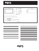
Wiring ConnectionsConnection Descriptions
PIN Description
V + +5V DPM Power Supply
GND DPM Power Supply Ground
DP COM Decimal Point Return
DP1 1XX.X
DP2 1X.XX
DP3 1.XXX
Input (+) Positive Input Signal
Input (–) Negative Input Signal
NC No Connection Required
HOLD Hold Last Display
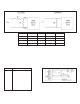
1. Floating Input, DPM65: The input common mode range is ±
1Vdc. If INPUT (–) is not directly conected to GND, a 10k
resistor network can be connected as shown to reduce unstable
readings.
2. Single-Ended Input, DPM65S: The 10K resistor network is not
required. The INPUT (–) is internally connected to GND.
Unused pins should be left open.
CAUTION: Damage to the unit can occur if the power source
polarity is reversed, or greater than 6V is applied
between pins 1 & 2.
DPM-65