
Instruction Manual

TERMINAL FUNCTIONS
CALIBRATION
SAFETY
1. + Positive current input.
2. Negative current input.
The meter is supplied calibrated to read 000 for 4mA loop current and 1000 for 20mA. C because the DPM 342
has a very wide adjustment range . Place the jumper link across LK1. This disables the offset adjustment to enable span adjustment to be made first.
After span adjustment is complete, the jumper link is removed and the offset adjustment is made. The jumper link is then used to display one of the
decimal pointsifnecessary.
Example tore-calibrate:Meterto read-40.0 for 4mA and150.0 for 20mA.
1. Calculate the span by subtracting the desired reading at 4mA from the desired reading at 20mA: -1500- (-400) = 1900
2. Short jumper link Lk1with the link headernormally used to select the desired Decimal Point.
Link Lk1is located above the screw terminals.
3. Apply 16mA between the + and - screw terminals.
4. Adjust the CAL potentiometer so the DPM 342indicates 1900.
5. Remove jumper link Lk1and place it back on the desired Decimal Point (DP1 in this case).
6. Apply 4mA between
8. Adjust CAL and OFF as necessary for optimum accuracy, by repeating steps 2 to 7.
-
alibration is carried out in two simple stages
the -and + screw terminals.
7. Adjust the OFF potentiometer so the DPM 342 indicates the desired reading at 4mA: -40.0
The user must ensure that the incorporation of the DPM into the user’s equipment conforms to the relevant sections of BS EN 61010 (Safety Requirements for
Electrical Equipment for Measuring, Control and Laboratory Use). Noinputs other than 4-20mA indicating loop current should be made.
PANEL FITTING
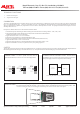
JUMPER LINKS:
In order to quickly and easily select the
required Decimal Point, the meter has several on-board jumper links.
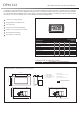
4-20mA
Transmitter
I+
+
I-
-
DPM 342
Specifications liable to change without prior warning DPM 342 Issue 2 July/2001 S.P.W. Applies to DPM 342/1
Connecting the DPM 342 to a 4-20mA Current Loop.
CURRENT LOOP CONNECTION:
The DPM 342 and
its backlighting are powered from the 4-20mA signal loop and need no
other power supply. Ensure correct polarity when connecting.
DP1
DP3
DP2
DP1
DP3
DP2
DP1
DP3
DP2
Locate the meter by passing it through the front of the panel cut-out and gently push until the rear of the bezel is flush with
the panel (DO NOT PUSH ON THE LCD). The snap-in lugs will now automatically hold the meter firmly in position. Take
care when inserting the meter, not to damage the current loop wires and not to short them on the panel.
Martel Electronics, Corp. P.O. Box 770 Londonderry, NH 03053
Toll Free: (800) 821-0023 Phone: (603) 434-1433 Fax: (603) 434-1653