
User Manual

DPM1AS-BL
3½DigitBacklitLCDVoltmeterModule
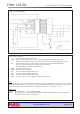
CIRCUIT DIAGRAM
www.lascarelectronics.com
PIN FUNCTIONS
1. V+ Positive powersupply tothe meter.
2. GND 0V power supply to the meter (3.0 to 7.5V meter power supply applications only).
3. V- Negative power supply to the meter (6.0 to 15.0V meterpower supplyapplications only).
4. BL- Connectto themeter's negative supply voltage to switch on the LED backlighting.
For metersupply voltagesabove 5V, add a series resistor Rs.
See Applications for suitable circuit diagrams.
5. INHI Positive measuring input.
6. INLO Negative measuring input.
7. DP1 Connectto XDP to display DP1 (199.9).
8. DP2 Connectto XDP to display DP2 (19.99).
9. DP3 Connectto XDP to display DP3 (1.999).
10. XDP Connect to pin 7, 8 or 9 to display required decimal point.
A negative supply is generated internally and mirrors the positive supply. For example: if V+ is +5V, then
the internally generated V- is -5V. When measuring with the input referenced to the same supply rail as
that of the panel meter, then the limitations on the input range are(V- +1.5V) to (V+ - 1.5V).
LCOM Normally Open. Connects INLO to COM.
LXDP Normally Closed. Cut thislink todisable the internal decimal point drive circuit and thereby
reduce the meter's current consumption.
Note:
Solder Links:
www.martelmeters.com
page 3 of 4