
Instruction Manual

2. Calibrator Interface
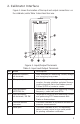
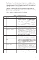
Figure 1 shows the location of the input and output connections on
the calibrator, while Table 1 describes their use.
Figure 1. Input/Output Terminals
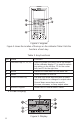
Table 1: Input and Output Terminals
No. Name Description
1, 2 Measure Isolated V, Input terminals for measuring current, voltage,
mA terminals and supplying loop power.
3 TC input/output Terminal for measuring, or simulating thermo-
couples. Accepts miniature polarized thermo-
couple plugs with flat in-line blades spaced
7.9 mm (0.312 in) center to center.
4,5 Source/Measure Terminals for sourcing and measuring voltage,
V,RTD 2W, Hz, frequency, pulse train, and RTDs
6,7 Source/Measure Terminals for sourcing and measuring current,
mA terminals, 3W 4W and performing RTD measurements with
3-wire or 4-wire setups.
8 Pressure module Connects calibrator to a pressure module for
connector pressure measurements.
9 Serial port Connects calibrator to a PC for uploading
data or remote control or to a serial printer
for printing calibration certificates.
5