DMC1400 Reference Manual
1. Introduction . . . . . . . . . . . . . . . . .1 1.1 Customer Service . . . . . . . . . . . . . . . . . . . 1 1.2 Standard Equipment . . . . . . . . . . . . . . . . . 1 1.3 Safety Information . . . . . . . . . . . . . . . . . . 2 2. Calibrator Interface . . . . . . . . . . .5 2.1 Main Display . . . . . . . . . . . . . . . . . . . . . . 6 2.2 Menu Bar . . . . . . . . . . . . . . . . . . . . . . . . . 8 2.3 Cursor Control / Setpoint Control . . . . . . 11 3. Using Measure Modes (Lower Display) . . . . . .
1. Introduction The Martel DMC1400 Multifunction Process Calibrator is a handheld, battery-operated instrument that measures and sources electrical and physical parameters. The calibrator has the following features and functions: • A dual display. The upper display is used for the measurement of volts, current, and pressure. The lower display can be used to measure volts, current, pressure, resistance temperature detectors (RTDs), thermocouples, frequency, and resistance, and to source pulse trains.
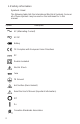
1.3 Safety information Symbols Used The following table lists the International Electrical Symbols. Some or all of these symbols may be used on the instrument or in this manual.
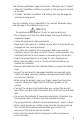
The following definitions apply to the terms “Warning” and “Caution”. • “Warning” identifies conditions and actions that may pose hazards to the user. • “Caution” identifies conditions and actions that may damage the instrument being used. Use the calibrator only as specified in this manual, otherwise injury and damage to the calibrator may occur. Warning To avoid possible electric shock or personal injury: • Do not apply more than the rated voltage. See specifications for supported ranges.
• When servicing the calibrator, use only specified replacement parts. • To avoid false readings, which could lead to possible electric shock or personal injury, replace the battery as soon as the battery indicator appears. • To avoid a violent release of pressure in a pressurized system, shut off the valve and slowly bleed off the pressure before you attach the pressure module to the pressure line.
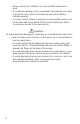
2. Calibrator Interface Figure 1 shows the location of the input and output connections on the calibrator, while Table 1 describes their use. Figure 1. Input/Output Terminals Table 1: Input and Output Terminals No. Name Description 1, 2 Measure Isolated V, mA terminals Input terminals for measuring current, voltage, and supplying loop power. 3 TC input/output Terminal for measuring, or simulating thermocouples. Accepts miniature polarized thermocouple plugs with flat in-line blades spaced 7.9 mm (0.
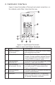
Figure 2. Keypad Figure 2 shows the location of the keys on the calibrator. Table 2 lists the functions of each key. Table 2. Key Functions No. Name Function 1 Function Keys F1, F2, F3 Used to operate the menu bar at the bottom of the calibrator display. F1 is used for selecting options in the left box, F2 for the center box, and F3 for the right box. 2 Home Returns to home menu on the menu bar. 3 Power Turns calibrator on and off.
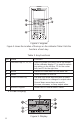
The display of the calibrator, shown in Figure 3, is divided into three main sections: the upper display, the lower display, and the menu bar. The upper display is used for measuring dc voltage, dc current with and without loop power, and pressure. The lower display can be used for both measuring and sourcing. The menu bar is used to setup both the upper and the lower display to perform the desired function. Table 3 explains the different parts of the display: Table 3: Display Functions No.
2.2 Menu Bar The parameters on the display are controlled by the menu bar, which is located at the bottom of the LCD. The function keys (F1, F2, and F3) are used to navigate through all the levels and choices of the menu bar. Refer to the menu tree for a clarification on the layout of all the levels. The top level of the menu is the home menu. It can be accessed anytime by pressing the HOME key. There are three variations of the home menu: the input home menu, the output home menu, and the pulse home menu.
The Document Mode selection menu is next. Its options are [DOCUMENT], [NEXT], and [DONE]. Choosing [DOCUMENT] enters the document mode menu system described in section 8 of this manual, [NEXT] proceeds to the next menu level, and [DONE] returns to the home menu. The Auto Function Menu is the next menu if you are in source mode. Its options are [AUTO FUNC], [NEXT] and [DONE]. [AUTO FUNC] allows you to adjust the Automatic Output Function parameters.
before it shuts off. [NEXT] proceeds to the clock menu, and [DONE] returns to the home menu. The Clock menu is the next menu displayed in the [MORE] menu sequence. Its options are [CLOCK], [NEXT], and [DONE]. Choose [CLOCK] to set the calibrator date and time as described in section 8 of this manual, [NEXT] to proceed to the terminal emulation menu, and [DONE] to return to the home menu. The Terminal menu is the last menu displayed after choosing [MORE] in the main menu.
The parameter selection menu is called up when [UPPER] or [LOWER] is selected from the main menu. It contains the following options: [SELECT], [NEXT], and [DONE]. When the display is selected, a parameter will start to flash. Use the [SELECT] option to change the parameter, and the [NEXT] option to switch to another variable. [DONE] returns to the home menu and enables the selected mode. 2.
Home Menu MENU LIGHT RAMP Selection Menu UPPER Parameter Selection SELECT NEXT LOWER MORE Document Mode Selection DONE DOCUMENT Home Menu Source Mode? Yes NEXT DONE Document Menus Auto Function Menu AUTO FUNC NEXT DONE No Frequency Out or Pulse mode? Yes Frequency Level Menu FREQ LEVEL NEXT DONE No RTD Custom mode? RTD Custom Menu Yes SET CUSTOM NEXT DONE No Either display in Pressure mode? Yes Pressure Zero Menu ZERO NEXT DONE No Contrast Menu CONTRAST NEXT DONE Au
3. Using Measure Modes (Lower Display) 3.1 Measuring volts and frequency Electrical parameters volts and frequency can be measured using the lower display. To make the desired measurements, follow these steps: 1. Switch to the lower display [LOWER] from Main Menu. 2. Select the desired parameter for measurement. 3. Connect leads as shown in Figure 5. Figure 5. Measuring Volts and Frequency with Input/Output Terminals 3.2 Measuring mA To measure mA follow these steps: 1.
described in Specifications section. The calibrator also has a Cold Junction Compensation (CJC) function. Normally this function should be ON and the actual temperature of the thermocouple will be measured. With CJC OFF, the calibrator will measure the difference between the thermocouple at the junction and at its TC input terminal. Note: CJC off mode should only be used when calibration is being done using an external ice bath. To use the thermocouple to measure temperature, follow these steps: 1.
The calibrator accepts two, three, and four wire inputs, with four wire input being the most accurate. To use the RTD option, apply the following steps: 1. Switch to lower display [LOWER] from Main Menu. 2. Select RTD from the primary parameters. Select [IN] from input/output control. 3. Choose 2, 3, or 4-wire connection [2W, 3W, 4W]. (4-wire allows for the most precise measurement) 4. Select RTD type from the sensor types. 5. Attach RTD leads as shown in Figure 8. Figure 8.
Caution To avoid mechanically damaging the pressure module, never apply more than 10 ft-lb. of torque between the pressure module fittings, or between the fittings an the body of the module. To avoid damaging the pressure module from overpressure, never apply pressure above the rated maximum printed on the module. To avoid damaging the pressure module from corrosion, use it only with specified materials. Refer to the pressure module documentation for material compatibility.
To adjust the calibrator, follow these steps: 1. Enter the pressure zeroing menu. 2. Select [ZERO ]. [SET REFERENCE ABOVE] will appear. Enter the pressure using the keypad. 3. The calibrator stores the Barometric zero offset in nonvolatile memory. The zero offset is stored for one absolute pressure module at a time. If a new absolute module is connected this process must be repeated. 4.
4.1-1 Stepping the current output To use the 25% function with mA output, follow these steps: 1. Select the lower display from the Main Menu, and choose mA. 2. Use the 25% key to cycle between 4 mA and 20 mA in 25 % intervals. 4.2 Using the Automatic Output Functions There are two automatic output functions, step and ramp. The selected function can be turned on and off using the Output Home Menu. The Automatic Output Function parameters can be set in the Auto Function Menu. Parameters include: 1.
4.3-1 HART™ Resistor Selection The DMC1400 can be set-up so that the 250 ohm resistor required for HART™ configuration devices resides inside the DMC1400. Enabling the DMC1400's internal 250 ohm resistor eliminates the need to manually add a series resistor during a HART™ calibration process. NOTE: When the DMC1400's internal 250 resistor is enabled, maximum load driving capability drops from 1000 ohms @ 20mA to 750 ohms @20mA. Enable/Disable Procedure 1.
2. Choose mA simulation from the primary parameters [mA 2W SIM], and enter the desired current. 3. Connect the 24V loop as shown in Figure 11. Figure 11. Connections for Simulating a Transmitter 4.5 Sourcing volts To source volts follow these steps: 1. Select lower display from the Main Menu. 2. Choose [VOLTS] from the primary parameters. Switch to input/output control and select output [OUT]. 3. Connect the leads for the voltage source terminals, as shown in Figure 12. 4.
4.6 Sourcing frequency To source a signal use these steps: 1. Switch to the lower display and select frequency from the primary parameters. 2. Select output, and than choose the frequency units. 3. Connect the leads to the frequency output terminals as shown in Figure 12. 4. Enter the desired frequency using the keypad. 5. To change the amplitude, select [FREQ LEVEL] from frequency level menu. 6. Enter the amplitude. 4.
Figure 13. Connections for Outputting Thermocouples 4.8 Sourcing Thermocouples To source a thermocouple use the following steps: 1. Connect the thermocouple leads to the appropriate polarized TC miniplug, and insert the plug into the TC terminals on the calibrator, as shown in Figure 13. 2. Select lower display from the Main Menu, and choose thermocouple [TC] from the primary parameters. 3. Choose output [OUT] from the input/output control. 4. Select the desired thermocouple type from the sensor types. 5.
4.9 Sourcing Ohms/RTDs To source an RTD, follow these steps: 1. Select lower display from the Main Menu, and choose [RTD] from the primary parameters. 2. Choose output [OUT] from the input/output control, and select RTD type from the sensor types. 3. Connect the calibrator to the instrument being tested, as in Figure 14. 4. Enter the temperature or resistance using the keypad. Figure 15. Using a 3- or 4-wire Connection for RTDs Note: The calibrator simulates a 2-wire RTD.
2. Enter the RTD custom setup main menu, and select [SET CUSTOM]. 3. Using the keypad, enter the values that the calibrator prompts for: minimum temperature, maximum temperature, R0, and the values for each of the temperature coefficients. The custom function uses the Calendar-Van Dusen equation for outputting and measuring custom RTDs. The coefficient C is only used for temperatures below 0°C. Only A and B coefficients are needed for the range above 0°C, so coefficient C should be set to 0.
5.2 Measuring current with loop power To test a 2-wire, loop powered transmitter that is disconnected from wiring, use the loop power function. This function activates a 24V supply in series with the current measuring circuit. To use this option proceed as follows: 1. Select [mA LOOP] as primary parameter in the upper display. 2. Connect the calibrator to transmitter current loop terminals, as shown in Figure 17. Figure 17. Connection Using Current Loop 5.
3. Gently remove the top half of the case from the bottom. 4. Figure 10a. shows the location of the HART™ jumpers. 5.3 Measuring Pressure Note: The DMC1400 is compatible with BETA Calibrator Pressure Modules. The accessory BPPA-100 is required for pressure measurement. Note: Pressure is not read from modules with frequency or pulse train mode enabled.
Figure 18. Measuring Pressure Transmitter Note: On high pressure modules engineering units normally associated with low pressure ranges such as, inH 2O, cmH2O, etc. are not valid selections. Selecting one of these units with a high pressure module attached will cause the display to read "----". 6. Using the Upper and the Lower Display for Calibration and Testing 6.
6.2 Calibrating an I/P Device The following steps show how to calibrate a device that controls pressure: 1. Select upper display from the Main Menu, and select pressure from the primary parameters. 2. Switch to lower display from the Main Menu, and select current source [mA out] from the primary parameters. 3. Connect the calibrator to the device as shown in Figure 20. The calibrator will simulate the transmitter current and measure the output pressure. 4. Enter a current using the keypad. Figure 20.
4. Connect the calibrator to the transmitter as shown in Figure 21. 5. Test transmitter at 0- 25- 50- 75- 100 % using the 25 % step function (25% key). Adjust the transmitter a necessary. To calibrate a different transmitter, follow the above steps with the exception of choosing TC on the lower display. Replace TC with the correct parameter for the transmitter. Figure 21. Calibrating a Transmitter 6.4 Calibrating a Pressure Transmitter To calibrate a pressure transmitter, use these steps: 1.
Figure 22. Calibrating a Pressure Transmitter 7. Remote Operation The calibrator can be remotely controlled using a PC terminal, or by a computer program running the calibrator in an automated system. It uses an RS-232 serial port connection for remote operation. With this connection the user can write programs on the PC, with Windows languages like Visual Basic to operate the calibrator, or use a Windows terminal, such as Hyper Terminal, to enter single commands.
7.1 Setting up the RS-232 Port for Remote Control Note: The RS-232 connection cable should not exceed 15m unless the load capacitance measured at connection points is less than 2500pF. Serial parameter values: 9600 baud 8 data bits 1 stop bit no parity Xon/Xoff EOL (End of Line) character or CR (Carriage Return) or both To set up remote operation of the calibrator on the Windows Hyper Terminal, connected to a COM port on the PC as in Figure 23, use the following procedure: 1.
2. To enable Remote with Lockout, type in REMOTE and LOCKOUT in either order. 3. To switch back to local operation enter LOCAL at the terminal. This command also turns off LOCKOUT if it was on. For more information on commands refer to the Remote Commands section. 7.3 Using Commands 7.3-1 Command types Refer to the Section on Remote Commands for all available commands. The calibrator may be controlled using commands and queries. All commands may be entered using upper or lower case.
Overlapped Commands Commands that require more time to execute than normal. The command *WAI can be used after the overlapped command to tell the calibrator to wait until the command finishes before executing the next command. For example: TRIG; *WAI Triggers the pulse train. Once the pulse train has been triggered, the calibrator can proceed to the next command. Sequential Commands Commands that are executed immediately after the are entered. This type includes most of the commands. 7.
Indefinite ASCII (IAD) Any ASCII characters followed by a terminator. For example: *IDN? returns MARTEL, ASC300, 250, 1.00 7.3-4 Calibrator Status Status registers, enable registers, and queues provide status information on the calibrator. Each status register and queue has a summary bit in the Serial Poll Status Byte. Enable registers generate summary bits in the Serial Poll Status Byte. The following is a list of registers and queues along with their function.
Event Status Enable Register (ESE) Enables and disables bits in the ESR. Setting a bit to 1 enables the corresponding bit in the ESR, and setting it to 0 disables the corresponding bit. Cleared at power reset. Bit assignments for the ESR and the ESE respectively are shown below. 15 14 13 12 11 10 9 8 0 0 0 0 0 0 0 0 7 6 5 4 3 2 1 0 PON 0 CME EXE DDE QYE 0 OPC PON Power On. Set to 1 if power was turned on and off before the Event Status Register was read. CME Command Error.
Error Queue If an error occurs due to invalid input or buffer overflow, its error code is sent to the error queue. The error code can be read from the queue with the command FAULT?. The error queue holds 15 error codes. When it is empty, FAULT? returns 0. The error queue is cleared when power is reset or when the clear command *CLS is entered. Input Buffer Calibrator stores all received data in the input buffer. The buffer holds 250 characters. The characters are processed on a first in, first out basis.
Table 6: Calibrator Commands Command Description CAL_START Puts the calibrator in calibration mode CJC_STATE Turns CJC on or off.
RTD_TYPE? Returns the RTD type RTD_WIRE Sets the number of wires used by the RTD mode.
InH2O4C Pressure in inches of water at 4°C InH2O20C Pressure in inches of water at 20°C CmH2O4C Pressure in centimeters of water at 4°C CmH2O20C Pressure in centimeters of water at 20°C Bar Pressure in bars Mbar Pressure in millibars KPal Pressure in kiloPascals InHg Pressure in inches of mercury at 0°C MmHg Pressure in millimeters of mercury at 0°C Kg/cm2 Pressure in kilograms per square-centimeter Table 8: Error codes Error Number Error Description 100 A non-numeric entry was receiv
parameters that may be entered with the command as well as what the output of the command is. 7.5-1 Common Commands *CLS Clears the ESR, the error queue and the RQS bit. Also terminates all pending operations. When writing programs, use before each procedure to avoid buffer overflow. *ESE Loads a byte into the Event Status Enable register. The command is entered with a decimal number that, when converted to binary, enables the right bits in the Event Status Register.
*OPC? Returns 1 when all operations are complete, and causes program execution to pause until all the operations are complete. For example: TRIG ; *OPC? will return a 1 when the pulse train initiated by TRIG is complete. *RST Resets the state of calibrator to the power-up state. All subsequent commands are held off until the execution of the command is complete. *SRE Loads a byte into the Service Request Enable register.
7.5-2 Calibrator Commands CAL_START Puts the calibrator in calibration mode. The main display will say CALIBRATION MODE and a calibration menu will be displayed on the terminal. CJC_STATE Turns Cold Junction Compensation (CJC) on or off, when the calibrator is in thermocouple (TC) mode. The command is used by adding ON or OFF after it. For example: CJC_ STATE OFF turns CJC off. CJC_STATE? Tells whether the Cold Junction Compensation in thermocouple mode is turned on or turned off.
CPRT_COEFB? Returns the number, which was entered for the first coefficient of the polynomial used in the custom RTD. Using the example above, CPRT_COEFB? Would return: -5.801900E-07 CPRT_COEFC This command is used for entering a custom RTD into the calibrator. The numeric value entered after the command will be set as the first coefficient of the polynomial used by the custom RTD. For example: CPRT_COEFC -5.8019E-12 enters -5.8019e-12 as coefficient A.
CPRT_MIN_T? Returns the value entered for minimum temperature in the range for a custom RTD. The above example would return: 0.000000E+00, CEL CPRT_R0 Sets the 0° resistance, R0, in the custom RTD. The value must be entered with a units label. Refer to the Parameter Units table for assistance. For example: CPRT_R0 100 OHM sets R0 to 100 ohms. CPRT_R0? Returns the value for the resistance in custom RTD. The above example would return: 1.
FREQ_TYPE When in frequency mode, sets the calibrator to output a continuous wave (Frequency Out), or a pulse train. To set the calibrator to continuous wave enter CONT after the command. To set the calibrator to pulse enter PULSE after the command. For example: FREQ_TYPE CONT will set the calibrator to FREQ OUT. Note: This command does not put the calibrator in frequency mode. Use the OUT command to put the calibrator in frequency mode.
LOCAL Restores the calibrator to local operation if it was in remote mode. Also clears LOCKOUT if the unit was in lockout mode. LOWER_MEAS Sets the lower display to measure mode. The command is followed by any of the parameters except for pulse and mA sim, which are source only. Enter DCI for mA, DCV for volts, TC for thermocouple, RTD for RTD, FREQUENCY for frequency, and PRESSURE for pressure.
PRES_UNIT? Returns the pressure units of both the upper and the lower display. For example if the unit on the upper display is bars, and on the lower it is psi, the command will return: BAR, PSI PULSE_CNT Sets the number of pulses the calibrator will produce when it is triggered while in pulse mode. For example; PULSE_CNT 3000 will set the number of pulses to 3000. PULSE_CNT? Returns the number of pulses in the pulse train.
wire. For example: RTD_WIRE 4W sets the connection to 4-wire RTD_WIRE? Returns the number of wires used in the RTD connection. SET_CLOCK yyyy mm dd hh nn ss Sets the calibrator date and time, where yyyy is the four digit year (2006 to 2100), mm is the two digit month (1 to 12), dd is the two digit day (1 to the number of days in the specified month), hh is the two digit hour in 24 hour format (0 to 23), nn is the two digit minute (0 to 59), and ss is the two digit second (0 to 59).
TAG_DNLD See the separate Tag Download and Upload Procedures manual for detailed instructions on using this command to download tag calibration test configuration data from a PC to the calibrator. TAG_UPLD See the separate Tag Download and Upload Procedures manual for detailed instructions on using this command to upload tag calibration test results to a PC from the calibrator. TAGS? Sends a list of all tag ID's in the calibrator to a PC.
TRIG Starts and stops the pulse train when the calibrator is in pulse mode. The parameters of the pulse train are set by commands PULSE_CNT, and FREQ_LEVEL. Entering TRIG initializes the train. Entering the command while the pulse train is running stops it. TRIG? Returns TRIGGERED if the pulse train is running, and returns UNTRIGGERED when the pulse train is not running. Returns NONE when the calibrator is not in pulse mode.
ZERO_MEAS Zeroes the attached pressure module. Enter the zeroing value in PSI after the command when zeroing an absolute pressure module. ZERO_MEAS? Returns the zero offset or the reference value for absolute pressure modules.
8. Document Mode 8.1 Introduction Document mode allows an instrumentation technician to create repeatable calibration tests for up to 50 tags while in the field, to download predefined calibration tests from a PC database for up to 50 tags before going to the field, or some combination of both types up to a maximum of 50 tags. Each test may consist of 1 to 21 user selectable test points, and may be repeated as many times as necessary to complete adjustment and calibration of the tag.
Once the last point has been tested, the As Found test automatically ends, the real time clock time stamp is saved, and the technician is prompted for changes to the tag identification data (any field but tag number which can not be changed). If test validation was selected, the technician has the option of displaying the As Found test results.
Document Mode Menu Tree Document Menus Function Selection Menu TEST REVIEW EXIT Home Menu Review Menu Test Selection Menu AS FOUND AS LEFT EXIT Home Menu As Left Menu As Found Tag Selection Menu NEW SELECT EXIT Downloaded Tag As Found Test As Found Setup Menu UPPER LOWER DONE A Parameter Selection SELECT 54 NEXT DONE Home Menu
A Frequency Out or Pulse Mode? Pulse/Frequency Level Menu Yes DONE No No Pulse Mode? Yes Pulse Parameter Menu FREQ Upper display is manual type? COUNTS DONE Upper Units Menu Yes DONE No Lower display is manual type? Lower Units Menu Yes DONE No Either display in pressure mode? Yes Pressure Zero Menu ZERO DONE No B 55
B Pulse mode? AF data collection – pulse trigger Yes TRIGGER READY No AF data collection – pulse stop STOP Manual Input or Output? AF data collection – manual entry Yes NEXT DONE ABORT LEFT KEY No B C Manual Output? Manual output entry Yes DONE BACK No Manual Input? Manual input entry Yes DONE No AF data collection – save test point 56 SAVE DONE B C ABORT LEFT KEY B BACK
C Tag ID field selection SELECT NEXT SAVE Tag field data entry DONE NEXT SAVE Save As Found data and time stamp Validate test results? YES NO Tolerance field selection SELECT DONE Tolerance field data entry DONE Show test results? YES NO View test results DONE Save AF results as AL? YES NO Document Menus Adjust Instrument? YES NO D E 57
Downloaded Tag As Found Test Either display in pressure mode? Yes Pressure Zero Menu ZERO DONE No K Pulse mode? Yes AF data collection – pulse trigger TRIGGER READY No AF data collection – pulse stop STOP Manual Input? Yes AF data collection – manual entry NEXT ABORT REPEAT LEFT KEY No K Manual input entry DONE No K Last data point? BACK AF data collection – save test point SAVE ABORT REPEAT LEFT KEY Yes K Save As Found test data and time stamp L 58
L Tag ID field selection SELECT NEXT SAVE Tag field data entry DONE NEXT SAVE Save Tag ID data changes Validating results? Yes Show test results? YES NO No View test results DONE Save AF results as AL? YES NO Document Menus Adjust Instrument? YES NO D E 59
D Either display in pressure mode? Pressure Zero Menu Yes ZERO DONE No Pulse mode? Adjust – pulse trigger Yes TRIGGER READY No Adjust – pulse stop STOP Adjust – monitor/step/enter UP DOWN AS LEFT E As Left Menu As Left tag selection SELECT EXIT Home Menu Already has AL results? Yes Overwrite AL results? YES NO No E Either display in pressure mode? No F 60 Yes Pressure Zero Menu ZERO DONE
F Pulse mode? Yes AL data collection – pulse trigger TRIGGER READY No AL data collection – pulse stop STOP Manual Input? Yes AL data collection – manual entry NEXT ABORT REPEAT LEFT KEY No F Manual input entry DONE No BACK AL data collection – save test point Last data point? SAVE ABORT REPEAT LEFT KEY Yes F Save As Left data and time stamp Validating results? Yes Show test results? YES NO No View test results DONE AL complete, adjustment required? YES D NO Document Menus
Review Menu Review Function Select VIEW PRINT CLEAR View Tag Select SELECT EXIT Print Tag Select SELECT EXIT View Tag DONE EXIT Review Menu G Clear Tag Select SELECT Confirm Tag Clear YES NO CLEAR ALL EXIT Confirm Clear All Tags YES NO G G Final Confirm Clear All Tags YES G 62 NO Review Menu
Function Selection Menu TEST REVIEW EXIT Review Function Select VIEW PRINT CLEAR Test Selection Menu AS FOUND AS LEFT EXIT Select Tag for Testing New Download Tag Source? Configure Upper and Lower Displays Select Tag for Testing Collect As Found Test Data Collect As Found Test Data Enter Tag Identification Data Optionally, Modify Some Tag Identification Data Collect As Left Test Data Optionally, Display Validation Results As Left Test Complete, adjustment required? Optionally, Enter Tag V
8.2 New Tag As Found Test 8.2.1 Setup At the main menu, press the MENU function key, followed by the MORE function key, followed by the DOCUMENT function key to display the first level document mode menu. Press the TEST function key to display the test selection menu. Press the AS FOUND function key to display the As Found Tag Selection menu which shows all uncalibrated downloaded tags. The letter U indicates an uncalibrated downloaded tag.
These two menus operate the same as the normal upper and lower type and parameter selection menus described earlier in this manual, except that they have two extra type selections, MANUAL IN and MANUAL OUT. The currently selected parameter field blinks (indicated by bold italicized text above). Press the SELECT function key to cycle through the possible selections for that field. Press the NEXT function key to move to the next parameter field.
Up to 5 characters may be entered for a unit description using a telephone style entry method. The four lower lines provide a mapping of the allowed alphanumeric characters to the numeric keypad keys. To enter a character press the corresponding numeric key multiple times to cycle through the mapped characters until the desired character is displayed. For example, to enter E, press the 8 key 3 times.
The value displayed on the top line is the current pressure reading adjusted with the current reference pressure. Enter the new reference pressure using the numeric keys followed by the ENTER key, or if satisfied with the current reference value press the DONE function key to bypass changing it. When satisfied with the pressure reference, press the DONE function key to continue.
Enter the new peak to peak voltage using the numeric keys followed by the ENTER key, or if satisfied with the current voltage press the DONE function key to bypass changing it. When satisfied with the voltage value, press the DONE function key to continue. Pulse train has two variable parameters, frequency and pulse count. Since the calibrator can only store one variable parameter per test, one of these must be set to a fixed value for all test points, while the other is changed.
analysis, it is suggested that the test points be evenly spaced across the test range and that they be entered in ascending order, descending order, ascending followed by descending, or descending followed by ascending. The prompt displayed during the test depends on the input and output types selected. Any combination which includes pulse train output has its own unique prompt sequence, as does any combination which includes a manual input, manual output, or both.
interrupted. Press the YES function key to abandon the data collected. Pulse Train Type Prompt When the input/output combination includes a pulse train output, the following is displayed for each test point. The current test type, AF for As Found, and point number are shown in the upper right corner of the display. Note that the point number is the next point to be tested and data has not been saved for it yet. Enter the output value to be generated using the numeric keys, followed by ENTER.
If the data displayed is correct, press the SAVE function key to save the data and step to the next point. The point number in the upper right increases to show that the test data is saved. If the pulse train or manual data must be corrected before saving it, press the LEFT ARROW key to change back to the TRIG/READY prompts and repeat the test.
If the calibrator input is not manual, wait for the displayed calibrator input value to settle and then press the NEXT function key to prompt for the manual entry(s) as described in the following subsection. If the calibrator input is manual, wait for the external device reading to settle and then press the NEXT function key to prompt for the manual entry(s) as described in the following subsection. Upon return from the manual entry prompts(s), the NEXT function key label changes to SAVE.
8.2.3 Identification Data Entry When the DONE function key is pressed at the data collection stage, the first page of the following two page identification data display is shown. Initially all data fields are blank, but after data is entered the current value of each field is shown to the right of its description. These two pages provide space to enter eight phrases of up to 16 characters each to describe the test that has been performed.
Up to 16 characters may be entered for the field using a telephone style entry method. The four lower lines provide a mapping of the allowed alphanumeric characters to the numeric keypad keys. To enter a character press the corresponding numeric key multiple times to cycle through the mapped characters until the desired character is displayed. For example, to enter E, press the 8 key 3 times.
validation should not be selected. Press the YES function key to validate the results. Press the NO function key to bypass validation and proceed to the test conclusion stage. When validation is selected, the following prompt is displayed showing the current settings for output zero and span, input zero and span, and the % span error tolerance. Initially the span tolerance is set to 0.25%, and the input and output values are set to the corresponding minimum and maximum test results values.
The overall test status display provides the option of displaying details for each test point. The overall test status is displayed on the top line. If all points passed, PASSED is displayed. If one or more points have failed, FAILED is displayed. Press the NO function key to bypass detail results display and proceed to the test conclusion stage. Press the YES function key to display the test details.
If pressure is selected on the upper or lower display, the pressure zero prompt is displayed first and operates as described under As Found Setup. The prompt displayed during the test depends on the input and output types selected. Any combination which includes pulse train output has its own unique prompt sequence. All other combinations are covered by a generic prompt. Generic Type Prompt A prompt similar to the following is displayed for each test point when the output is not pulse train.
The PT in the upper right corner of the display indicates that this is the adjustment display. If an As Found data point is selected, its number is displayed. If a user entered value is selected, two dashes are displayed. Use the numeric keys, followed by ENTER, to enter a user value for generation, or press the READY function key to proceed to the next menu where the UP and DOWN function keys can be used to scroll through the As Found data points. Press the TRIG function key to generate the pulse train.
8.4 Downloaded Tag As Found Test 8.4.1 Tag Selection At the main menu, press the MENU function key, followed by the MORE function key, followed by the DOCUMENT function key to display the first level document mode menu. Press the TEST function key to display the test selection menu. Press the AS FOUND function key to display the As Found Tag Selection menu which shows all uncalibrated downloaded tags. Tag numbers are displayed on multiple pages, six tags to a page.
1) The test outputs can not be changed, they will be the predefined values that were downloaded. For pressure and manual output types, the downloaded value is displayed for the technician to set it on the external source. For all other output types, the calibrator automatically generates the As Found value. 2) Once the SAVE function key is pressed for the last test point, the process automatically proceeds to the identification data entry stage.
Press the TEST function key to display the test selection menu. Press the AS LEFT function key to display the tag selection prompt which shows all previously calibrated tags available for recalibration. Tag numbers are displayed on multiple pages, six tags to a page. Press the UP ARROW and DOWN ARROW keys to scroll the tag selector highlight one tag at a time, scrolling from page to page, cycling from top to bottom of the list and vice versa.
2) The test outputs can not be changed, they will be the same as the As Found values. This ensures that the As Found and As Left test results line up when being compared later. For pressure and manual output types, the As Found value is displayed for the technician to set it on the external source. For all other output types, the calibrator automatically generates the As Found value.
The letter U indicates an uncalibrated downloaded tag, the remainder have been calibrated. Tag numbers are displayed on multiple pages, six tags to a page. Press the UP ARROW and DOWN ARROW keys to scroll the tag selector highlight one tag at a time, scrolling from page to page, cycling from top to bottom of the list and vice versa. Use the LEFT ARROW and RIGHT ARROW keys to scroll the tag selector highlight one page at a time, cycling from top to bottom of the list and vice versa.
during testing, which was with respect to the calibrator. Press the DONE function key to return to the tag selection menu. Press the EXIT function key to return to the review selection menu. 8.7 Printing Test Results At the main menu, press the MENU function key, followed by the MORE function key, followed by the DOCUMENT function key to display the first level document mode menu. Press the REVIEW function key to display the review selection menu.
8.8 Clearing Test Results At the main menu, press the MENU function key, followed by the MORE function key, followed by the DOCUMENT function key to display the first level document mode menu. Press the REVIEW function key to display the review selection menu. Press the CLEAR function key to display the tag selection prompt and clear menu options. To erase all tags from the calibrator memory, press the CLEAR ALL function key. Additional prompts are displayed to confirm the request.
Initially the date and time values displayed on the top line are the precise clock setting when the screen was first displayed. After that they are static values representing any data changes made. The clock is not updated until the SAVE function key is pressed. For the most accurate setting it is recommended that all values but the seconds be entered first, then enter a seconds value slightly ahead of the current time, and finally press the SAVE function key exactly when the entered seconds is reached.
• Sufficient extra disk space for storage of tag reports 9.2 Installation Insert the Video Tutorial CD into your PC's drive. A menu will be automatically displayed. Choose the menu option "Install Martel USV Utility Software." Follow the on-screen prompts to complete the installation. As an alternative, use Explorer to browse to the "\Martel USV" directory on the CD and run SETUP.EXE. Follow the on-screen prompts to install the application. 9.
to select the communications port to which the calibrator is connected. The Help menu contains the application help, support, and program information. 9.4 File Menu Initially USV is set to store reports in the root folder 'Martel USV' within the 'My Documents' folder. If you wish to store them into another folder, navigate to the alternate folder before saving the first report. From then on, until a further alternate folder is chosen, that folder will be the default for storage.
exist within the root directory, the tag subdirectory is created and the file is saved there. If the reports were uploaded from a calibrator, the file extension is TXT or CSV depending on the report format selection on the Upload menu at the time the reports were uploaded. If the reports were loaded from a file, the file extension is set the same as that of the source file. Print Print the tag calibration reports contained in the Reports list box.
Selected Tag Reports Upload selected tag calibration reports from the calibrator into the Reports list box. Before using this function, upload a list of the tag configurations contained in the calibrator using the Tag ID's function above. In the Tag ID's list box, highlight the tags which are to be uploaded, and then select this function to upload them. The Reports list box is cleared before the upload. Use the Configure menu to select the communications port.
9.6 Erase Menu All Tags Erase all tag configurations from the calibrator. Both list boxes are cleared after the erasure. Use the Configure menu to select the communications port. Selected Tags Erase selected tag configurations from the calibrator. Before using this function, upload a list of the tag configurations contained in the calibrator into the Tag ID's list box using the Tag ID's function on the Upload menu.
provides a Cancel button for terminating the download. As the download proceeds, a right angle bracket indicates the tag presently being processed, and the status is displayed as Loading. All tags not yet downloaded have status Pending. If a tag can not be downloaded for some reason, an error message is displayed explaining the problem and the tag status shows FAILED. All successfully downloaded tags have status Loaded.
the tag is selected, or directly if the report file contained a single tag, the configuration data is extracted and presented in a dialog screen with the tabs Identification, Instrument Input, Instrument Output, Tolerance, and Test Points for modification of the configuration data. This dialog screen is described in detail in section 9.9 below. When complete, the configuration is saved into a user named file with the fixed extension UTG. Display/Print Display a tag configuration, and optionally print it.
COM Port The communications port is selected by clicking on one of the following menu items. The selected port is indicated by the menu item with the checkmark, and is also displayed on the status line at the bottom of the screen. Use COM1 Use COM2 Use COM3 Use COM4 Use COM5 Use COM6 Use COM7 Use COM8 9.9 Tag Configuration Details Tag Identification Tab The Tag ID field is required and must not contain a space as its first character. The remaining fields are optional.
text string for it as documented in the user manual addendum accompanying your calibrator. The CJ field appears only for the Thermocouple type. It contains a drop down list presenting all of the available options for a standard calibrator. Select the cold junction option corresponding to the instrument to be calibrated.
documented in the user manual addendum accompanying your calibrator. The Wires field appears only for the RTD type. It contains a drop down list presenting all of the available options for a standard calibrator. Select the connection option corresponding to the instrument to be calibrated. If your calibrator contains special software implementing a non?standard connection option, enter the text string for it as documented in the user manual addendum accompanying your calibrator.
9.10 Group Configuration Details The display contains two lists. The leftmost contains all available tags which are not presently members of the group. The rightmost contains the present group members. All tags which are members of the group must reside in the same directory as the group. To add tags to the group, highlight them in the available list and click the right arrow. To add a single tag, double click it. To remove tags from the group, highlight them in the group list and click the left arrow.
10. Specifications All measurements apply at 23°C ± 5°C. unless specified otherwise. Outside of this range the stability of the measurements is ± 0.005%of reading/°C. Table 9: General Specifications Operating Temperature -10°C to 50° Storage Temperature -20°C to 70°C Power 4 X AA batteries; Alkaline or optional rechargeable Low battery warning Yes Serial Communications Yes, ASCII CE - EMC EN50082-1: 1992 and EN55022: 1994 Class B Safety CSA C22.2 No. 1010.
Table 13: Resistance Measurement Range Accuracy (% of reading ± floor) Ohms low 0.00W - 400.0W 0.015% ± 0.03W Ohms high 401.0W - 4000.0W 0.015% ± 0.3W Table 14: Resistance Source Range Ohms low Ohms high Excitation Current Accuracy (% of reading ± floor) 5.0W - 400.0W 0.1mA - 0.5mA 0.015% ± 0.1W 5.0W - 400.0W 0.5mA - 3mA 0.015% ± 0.03W 400W - 1500W 0.05mA - 0.8mA 0.015% ± 0.3W 1500W - 4000W 0.05mA - 0.4mA 0.015% ± 0.3W Note: Unit is compatible with smart transmitters and PLCs.
TC type XK BP Range (°C) -200.0 - 800.0 0.0 - 800.0 800.0 - 2500.0 -200.0 - 0.0 0.0 - 900.0 L U -200.0 - 0.0 0.0 - 600.0 N -200.0 - 0.0 0.0 - 1300.0 Accuracy 0.2 0.9 2.3 0.25 0.2 0.5 0.25 0.8 0.4 All TC errors include CJC errors CJC error outside of 23 ± 5°C is 0.05°C/°C (In °C add .2 for cold junction compensation error.
RTD Type Range (°C) Uncertainty Miniumum Maximum 1 year (°C) PT3916, 100 ohm -200 -190 0.08 -190 -80 0.10 -80 0 0.11 0 100 0.13 100 260 0.17 260 300 0.17 300 400 0.19 400 630 0.25 PT385, 200 ohm -200 -80 0.40 -80 0 0.42 0 100 0.45 100 260 0.45 260 300 0.52 300 400 0.53 400 630 0.66 PT385, 500 ohm -200 -80 0.18 -80 0 0.19 0 100 0.21 100 260 0.25 260 300 0.26 300 400 0.29 400 630 0.34 PT385, 1000 ohm -200 -80 0.10 -80 0 0.12 0 100 0.14 100 260 0.17 260 300 0.18 300 400 0.19 400 630 0.25 NI120 -80 260 0.
11. Maintenance / Warranty 11.1 Replacing Batteries Replace batteries as soon as the battery indicator turns on to avoid false measurements. If the batteries discharge too deeply the DMC1400 will automatically shut down to avoid battery leakage. Note: Use only AA size alkaline batteries or optional rechargeable battery pack. 11.2 Cleaning the Unit Warning To avoid personal injury or damage to the calibrator, use only the specified replacement parts and do not allow water into the case.
MRBK-AA Batteries Set of 4 AA 2500 mAH Nickel-Metal Hydride 1001-9V Battery Adapter/Charger 11.5 Warranty Martel Electronics Corporation warrants all products against material defects and workmanship for a period of twelve (12) months after the date of shipment. Problems or defects that arise from misuse or abuse of the instrument are not covered. If any product is to be returned, a "Return Material Author ization" number must be obtained from our Customer Service Department.
www.martelcorp.com e-mail: sales@martelcorp.