
User guide


FCS86 SURFACE SHARK™ FLOOR STRIPPER PAGE 13
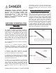
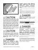
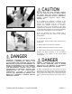
Use of a straight beveled scoring blade with
the cutting wings positioned down and
against the work surface can result in
unrepairable surface damage and personal
injury.
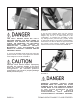
FIGURE 7
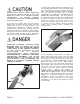
INSTALLING A BLADE TO THE FLOOR
STRIPPER
Tools required: 1 each, 5/32 inch T-handled Allen
wrench provided with the machine.
Parts required: 1 each, blade appropriate for the job
application
WHEN INSTALLING OR REMOVING A BLADE
T O / F R O M T H E F L O O R
STRIPPER ALWAYS WEAR THE
APPROPRIATE SAFETY EYEWEAR,
GLOVES, LEATHER SHOES AND LONG
PANTS TO MAXIMIZE PERSONAL
PROTECTION FROM THE SHARP EDGE(S).
IMPROPER CONTACT WITH A SHARP EDGE
CAN RESULT IN PROPERTY DAMAGE
AND/OR PERSONAL INJURY.
1) Properly disconnect the extension cord or the Floor
Stripper from the power source.
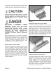
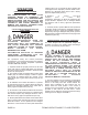
2) To place the operator handle in the work position,
move the handle upright so that the ball-detent pins
can be inserted through the operator handle and main
frame. Determine the ball-detent pins are inserted
through the operator handle and main frame to fully
expose the ball detent. FIGURE 8.
FIGURE 8
THE BALL DETENT MUST BE FULLY
EXPOSED AGAINST THE MAIN FRAME TO
PROVIDE THE PROPER PIN RETAINING
FORCE. AN IMPROPER PIN RETAINING
CONFIGURATION CAN RESULT IN
UNEXPECTED OPERATOR HANDLE
MOVEMENT. THIS OCCURRENCE CAN
RESULT IN PROPERTY DAMAGE AND/OR
PERSONAL INJURY.
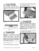
3) Loosen the threaded handle knobs and extend the
operator handle out until it stops against the threaded
studs. Retighten the knobs. FIGURE 9.
FIGURE 9