OPERATOR MANUAL Includes Safety, Service and Replacement Part Information Model FCS86 SURFACE SHARK™ Floor Stripper Do not discard this manual. Before operation, read and comprehend its contents. Keep it readily available for reference during operation or when performing any service related function. When ordering replacement parts, please supply the following information: model number, serial number and part number. Marshalltown, IA Phone 800-888-0127 / 641-753-0127 Fax 800-477-6341 / 641-753-6341 www.
MARSHALLTOWN SURFACE SHARK™ FLOOR STRIPPER WARRANTY PROGRAM PURPOSE It is the intention of Marshalltown Company to supply products to the marketplace that reflect the highest standards for materials, design and manufacture. Each original customer is entitled to receive coverage as described by the current limited warranty program for the product(s) purchased, regardless of where it (they) was (were) originally purchased.
Table of Contents DESCRIPTION PAGE Notice to Operators.................................................................................................................. 4 OperatOR Instructional Data Sheet................................................................................... 5 Safety Precautions Preparation........................................................................................................................................... 7 Operation.......................................
Notice to Operators IF YOU CAN NOT READ OR DO NOT FULLY UNDERSTAND THE CONTENTS OF THIS MANUAL, PLEASE CONTACT THE FACTORY FOR PROPER ASSISTANCE BEFORE ATTEMPTING TO OPERATE THIS PRODUCT. SI TU NO PUEDES LE’ER O NO COMPRENDES EL CONTENIDO DE ESTE MANUAL FAVOR DE PONERSE EN CONTACTO CON LA. FABRICA PARA ASSISTENCIA- A PROPIA ANTES DE INTENTAR PARA OPERAR ESTE PRODUCTO.
side effects of utilizing a Floor Stripper. A potential operator with a chronic back related problem or a history of back and/or other medically related problems should not attempt to utilize the Floor Stripper. Use of the Floor Stripper may only aggravate this and any other medically related problem.
4) LOCAL LAWS, REGULATIONS AND CUSTOMS RESEARCHED FOR AND/OR BY THE OWNER OF THE FLOOR STRIPPER AND DEEMED APPLICABLE TO THE SAFE AND PROPER USE AND/OR OPERATION OF THE FLOOR STRIPPER FOR ANY SPECIFIC JOB APPLICATION. 5) FORMALIZED MAINTENANCE PROGRAM FOR THE FLOOR STRIPPER TO BE DEVISED BY THE OWNER OF THE FLOOR STRIPPER IN ACCORDANCE WITH, BUT NOT NECESSARILY LIMITED TO, THE SPECIFICATIONS, GUIDELINES AND OPERATIONAL INFORMATION CONTAINED IN THE APPLICABLE OPERATOR MANUAL.
Safety Precautions THE FOLLOWING SAFETY PRECAUTIONS PROVIDE SOME COMMON SENSE GUIDES TO PROMOTE SAFETY AND EFFICIENCY WITH THE FLOOR STRIPPER. NO WARRANTY, GUARANTEE OR REPRESENTATION IS MADE BY THE MANUFACTURER AS TO THE ABSOLUTE CORRECTNESS OR SUFFICIENCY OF ANY INFORMATION OR STATEMENT. THESE SAFETY PRECAUTIONS ARE INTENDED TO DEAL PRINCIPALLY WITH COMMON PRACTICES AND CONDITIONS ENCOUNTERED IN THE USE OF THE FLOOR STRIPPER AND ARE NOT INTENDED TO BE ALL INCLUSIVE.
nerve and circulation damage and tissue necrosis. Antivibration systems do not guarantee that you will not sustain Whitefinger Disease. Therefore, continuous and regular users should closely monitor the condition of their hands and fingers. After each period of use, exercise to restore normal blood circulation. If any of the symptoms appear, seek medical advice immediately. 7) Clothing must be sturdy and snug fitting, but allow complete freedom of movement.
the potential for property damage and/or personal injury. Special care must be exercised on slippery conditions and on difficult, uneven surfaces. Watch for cracks, high spots and other surface irregularities. Keep proper footing and balance at all times. The normal use of this machine is on level surfaces. Other terrains can be dangerous and should be avoided. Only properly trained operators should attempt these techniques.
filed within a specific time period. If missing parts are detected, notify your dealer or the Customer Service Department who will assist you in obtaining them. Check all fasteners for proper security. Consult a fastener torque chart for the proper torque value if any fastener is found to require retorquing. INSTALLATION OF THE ADJUSTABLE SECTION OF THE OPERATOR HANDLE 3) Remove the threaded knobs from the fixed section of the operator handle.
Combinations of blade or accessory attachment type, job site conditions, and feed rates are direct factors that will also determine the overall success of the job application. improper knob tension and / or improperly securing the operator handle to the main frame can result in an unstable platform configuration . an unstable platform configuration can result in property damage and / or personal injury .
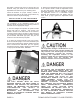
A protective covering is provided to protect the blade cutting edge from external damage and minimize the potential for property damage and/or personal injury. Store the blade with the protective covering properly installed to minimize the effects of external damage to the cutting edge and the potential for property damage and/or personal injury. FIGURE 5 THE BLADE IS EXTREMELY SHARP.
Use of a straight beveled scoring blade with the cutting wings positioned down and against the work surface can result in unrepairable surface damage and personal injury. can be inserted through the operator handle and main frame. Determine the ball-detent pins are inserted through the operator handle and main frame to fully expose the ball detent. FIGURE 8. FIGURE 8 FIGURE 7 INSTALLING A BLADE TO THE FLOOR STRIPPER Tools required: 1 each, 5/32 inch T-handled Allen wrench provided with the machine.
Improper knob tension and/or improperly securing the operator handle to the main frame can result in an unstable platform configuration. An unstable platform configuration can result in property damage and/or personal injury. 4) Tilt the Floor Stripper back until the operator handle comes in contact with the surface. The Floor Stripper may not be in a stable position in this configuration.
EXTREME CAUTION WHEN REMOVING AND/OR REINSTALLING THE PROTECTIVE COVER. STORE THE BLADE WITH THE PROTECTIVE COVER PROPERLY INSTALLED TO MINIMIZE THE POTENTIAL FOR BLADE DAMAGE AND/OR PERSONAL INJURY. 7) Return the Floor Stripper to its normal operating position. 8) Determine that the ON/OFF switch located on the operator handle is in the OFF position. If the Floor Stripper is to be used immediately, then reconnect the extension cord or Floor Stripper to the power source.
FIGURE 13 FIGURE 14 THE BALL DETENT MUST BE FULLY EXPOSED AGAINST THE MAIN FRAME TO PROVIDE THE PROPER PIN RETAINING FORCE. AN IMPROPER PIN RETAINING CONFIGURATION CAN RESULT IN UNEXPECTED OPERATOR HANDLE MOVEMENT. THIS OCCURRENCE CAN RESULT IN PROPERTY DAMAGE AND/OR PERSONAL INJURY. 4) Tilt the Floor Stripper back until the operator handle comes in contact with the surface. The Floor Stripper may not be in a stable position in this configuration.
UNEXPECTED MOVEMENT CAN ALLOW THE MACHINE TO FALL BACK TO THE WORK SURFACE. THE RESULT CAN BE PROPERTY DAMAGE AND/OR PERSONAL INJURY. 5) Reinstall the protective blade cover. Exercise extreme caution when removing and/or reinstalling the protective cover. Use the T-handled Allen wrench to loosen the button head cap screws which secure the blade between the fence plate and exciter plate. Remove the blade and store in an appropriate location.
Operation OPERATIONAL DISCLAIMER THE MANUFACTURER OF THE FLOOR STRIPPER MAKES NO WARRANTY OR GUARANTEE THAT IT IS MERCHANTABLE AND/OR SUITABLE FOR ANY SPECIFIC JOB APPLICATION AND THAT IT WILL HAVE THE CAPABILITY AND POWER REQUIRED TO REMOVE ANY SPECIFIC COVERING FROM ANY SPECIFIC WORK SURFACE.
Do not drop the Floor Stripper directly upon the exciter plate. Direct impact against the exciter plate can result in damage to components including the plate, elastomeric rubber mounts, electric motor shaft, bearings, etc. FIGURE 16 2) To minimize the possibility of damage to the Floor Stripper, always transport in its normal, upright position. All equipment must be secured in/on vehicles with suitable strapping or tie-downs. Personnel should not be transported in the same compartment as equipment.
ADJUSTING THE OPERATOR HANDLE HEIGHT The Floor Stripper incorporates a handle that can be adjusted to compensate for variances in operator height. Handle height can be infinitely varied between the stop limits. No external tools are required. Correct handle height can increase overall machine productivity and reduce operator fatigue. 1) Loosen the handle knobs located at the rear of the handle. Extend the knobs out approximately 1/2 inch (13 mm). FIGURE 18. FIXED SECTION OF THE OPERATOR HANDLE.
7) Determine that the power source receptacle to be utilized is properly grounded. This can be accomplished with proper testing equipment and procedures. If there are any questions regarding the suitability of a specific power receptacle, contact your dealer or our Customer Service Department for assistance BEFORE utilizing the Floor Stripper. There is no charge for this service. A qualified electrician may need to be consulted.
If the Floor Stripper and/or an individual component/accessory does not appear to be functioning properly, STOP and do not further operate the Floor Stripper until the proper corrective action has been completed. If there are any questions regarding the proper operation of the Floor Stripper, contact the Customer Service Department BEFORE further utilization. There is no charge for this service. FIGURE 20 11) The Floor Stripper is not equipped with a centrifugal clutch assembly.
WORK SURFACE. CONTACT WITH SUCH OBJECTS CAN LEAD TO LOSS OF MACHINE CONTROL, RESULTING IN PROPERTY DAMAGE AND/OR PERSONAL INJURY. ALWAYS MAINTAIN PROPER CONTROL OF THE FLOOR STRIPPER. IF AN OPERATOR LOOSES CONTROL OF THE MACHINE, A “RUNAWAY” FLOOR STRIPPER CAN RESULT IN PROPERTY DAMAGE AND/OR PERSONAL INJURY. BECAUSE OF THE UNIQUE OPERATING CHARACTERISTICS OF THE FLOOR STRIPPER, THERE IS NO PROVISION FOR THE ELECTRIC MOTOR TO AUTOMATICALLY STOP IF THE OPERATOR FAILS TO MAINTAIN PROPER CONTROL.
Keep feet a comfortable distance apart to help provide stability and locomotion force. A proper operator position is depicted in FIGURE 23. Improper operator positions are depicted in FIGURES 24 and 25. The proper and improper operator positions depicted in this manual are not all inclusive. FIGURE 23 4) The wide variety of potential covering materials along with the corresponding variety of job site environments, makes it impossible to develop a standardized operating procedure for the Floor Stripper.
THE CREATION OF DUST AND OTHER FOREIGN PARTICLE CONTAMINATION FROM THE COVERING REMOVAL PROCESS CAN RESULT IN PROPERTY DAMAGE AND/OR PERSONAL INJURY. FOR SUCH OPERATING CONDITIONS, ALWAYS WEAR A NIOSH/MSHA APPROVED DUST/MIST RESPIRATOR AND APPROPRIATE SAFETY RELATED APPAREL. CONSULT APPLICABLE OSHA REGULATIONS FOR SPECIFIC INFORMATION. FIGURE 26 EXERCISE EXTREME CAUTION WHEN SHARPENING THE BLADE. CLAMP THE BLADE FIRMLY IN THE VICE.
WATER OR OTHER CONDUCTIVE MATERIALS DEPOSITED ON THE WORK SURFACE INCREASES THE ELECTROCUTION POTENTIAL FOR THE OPERATOR AND/OR ASSOCIATED WORK PERSONNEL. DETERMINE THE FLOOR STRIPPER IS PROPERLY GROUNDED (NO FAULTS), THE EXTENSION CORD IS FREE OF CUTS, ABRASIONS, EXPOSED CABLE STRANDS AND THAT THE GFI PROPERLY FUNCTIONS TO ELIMINATE FAULT CONCERNS. IMPROPER MACHINE GROUNDING, EXTENSION CORDS AND/OR GFI CAN RESULT IN PROPERTY DAMAGE AND/OR PERSONAL INJURY.
REPLACE ANY DAMAGED WITH A FACTORY REPLACEMENT PART ONLY. FIGURE 27 5) Typically, adhesive/mastic densities or thickness change on the job site usually as a result of application rates on the work surface. This, in turn directly affects bond densities and thickness. As these factors change, the blade angle can be adjusted with the Back Saver™ Blade Control System to help optimize covering removal rates.
Service PREVENTATIVE MAINTENANCE CHECK LIST The normal operation of the Floor Stripper produces extreme dirt and dust, along with levels of random vibration. Before operating the Floor Stripper, the following service list should be accomplished. This list is for reference only and is not intended to be all inclusive.
LUBRICATION REQUIREMENTS Parts Required: 1 each, standard grease gun filled with one of the following: ESSO Beacon 325, Shell Alvania #2, Chevron SRI, or equivalent. 1 each, container of dry film lubricant. 1) Lubricate the caster wheel bearings with a dry film lubricant only. Dry film lubricants dry immediately upon contact. Use sparingly. Excess lubricant will attract the fine grained, powdered materials described and directly affect bearing service life.
Troubleshooting ACCELERATED EXCITER SHAFT BEARING WEAR AND/OR FAILURE ELECTRIC MOTOR Misaligned and/or improperly tensioned bearing housing/mounting surfaces. Replace bearing and realign bearing housing/mounting surface. MOTOR FAILS TO START ON/OFF switch in the OFF position. Place switch in the ON position. Bent electric motor shaft. Replace motor. Thermal protection switch activated. Allow time for motor to cool.
Storage Specifications Proper procedure for long term storage of the Floor Stripper will protect it against the effects of corrosion and damage. If the Floor Stripper is not to be operated for a period of 30 days or more, proceed to store as follows: FRAME 1) Never store the Floor Stripper with the blade installed. Remove the blade from the Floor Stripper per the procedures outlined in this manual.
FCS86 SURFACE SHARK™ Floor Stripper Replacement Parts Diagrams Section PAGE 32 FCS86 SURFACE SHARK™ FLOOR STRIPPER
FCS86 SURFACE SHARK™ FLOOR STRIPPER PAGE 33
Frame Assembly FCS86 SURFACE SHARK™ Floor Stripper PAGE 34 FCS86 SURFACE SHARK™ FLOOR STRIPPER
Frame Assembly FCS86 SURFACE SHARK™ Floor Stripper REFERANCE NUMBER PART NUMBER DESCRIPTION QTY 1 2 3 4 5 6 7 8 MFCS86-0011 MFCS86-0170 MFCS86-0230 MFCS86-0022 MFCS86-0191 MFCS86-0111 MFCS86-0101 MFCS86-0031 1 1 1 1 1 1 1 1 9 10 11 12 13 14 15 16 17 18 19 20 21 22 MFCS86-0331 M15050700 M16050000 M17040000 M48050800 M18060000 M86070000 MFCS86-0321 MFCS86-0071 M60071000 M63030800 M87061800 M55050600 MFCS86-0311 23 24 25 26 27 28 29 30 31 32 33 34 35 36 37 38 39 40 41 42 43 44 45 46 M15060800 M160600
Operator Handle Assembly FCS86 SURFACE SHARK™ Floor Stripper PAGE 36 FCS86 SURFACE SHARK™ FLOOR STRIPPER
Operator Handle Assembly FCS86 SURFACE SHARK™ Floor Stripper REFERENCE NUMBER 1 2 3 4 5 6 7 8 9 10 11 12 13 14 15 16 17 18 19 20 21 22 23 24 25 26 PART DESCRIPTION NUMBER MFCS86-0180 Handle, Lower MFCS86-0160 Handle, Top MFCS86-0140 Crank Assembly MFCS86-0290 Grip, Rubber MSP8-0120 Knob, Handle M15081600 Screw, Cap, 1/2-13 UNC x 2", Plated MFCS86-0120 Hose, U-Joint MFCS86-0460-010 Bushing, Strain Relief M660-0410 Bushing, Bronze, 3/4" ID MKIC-172 Ring, Kick-out M62081400 Bolt, Shoulder, 1/2" x 1-3/4" MF
Adjustable Axle Assembly FCS86 SURFACE SHARK™ Floor Stripper PAGE 38 FCS86 SURFACE SHARK™ FLOOR STRIPPER
Adjustable Axle Assembly FCS86 SURFACE SHARK™ Floor Stripper REFERENCE NUMBER 1 2 3 4 5 6 7 8 9 10 11 12 13 14 15 16 PART DESCRIPTION NUMBER MFCS86-0060 Axle MFCS86-0130 Axle Arm Assembly MFCS86-0050 Screw, Jack M21010800 Pin, Roll, Spiral, 1/8" x 1" MFCS86-0240 Wheel, 8" M550-0590 Fitting, Grease M660-0410 Bushing, Bronze, 3/4" ID M62122400 Bolt, Shoulder, 3/4" x 3” M200682 Washer, Fiber M62121200 Bolt, Shoulder, 3/4" x 1-1/2" M18100000 Nut, Hex, 5/8-11 UNC, Plated M17100000 Washer, Flat, 5/8", Plated
Replacement Cutting Blades FCS86 SURFACE SHARK™ Floor Stripper 1 2 3 PAGE 40 FCS86 SURFACE SHARK™ FLOOR STRIPPER
Replacement Cutting Blades FCS86 SURFACE SHARK™ Floor Stripper REFERENCE NUMBER PART DESCRIPTION NUMBER 1 MFCS86-1100 Blade, Straight (4 x 6") (General Purpose Removal Projects On Both Concrete And Wood Surfaces) 2 MFCS86-1300 Blade, Straight (3 x 10") (General Purpose Removal Projects On Both Concrete And Wood Surfaces) 3 MFCS86-1500 Blade, Scoring (8" Wide) (Glued Carpets And Sheet Type Linoleum, Rubber, PVC, Etc.
NOTES PAGE 42 FCS86 SURFACE SHARK™ FLOOR STRIPPER
NOTES FCS86 SURFACE SHARK™ FLOOR STRIPPER PAGE 43
Marshalltown, IA Phone 800-888-0127 / 641-753-0127 Fax 800-477-6341 / 641-753-6341 www.marshalltown.