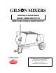
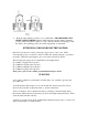
GILSJ JN MIXERS MORTAR-PLASTER MIXER MODEL: 800MP-NEW STYLE OPERATOR’S GUIDE & PARTS MANUAL GILSJ J N MIXERS BY 4343 Easton Road · St. Joseph, MO 64503 816-233-4840 · 800-253-3676 Fax 816-233-4624 · 888-253-3676 E-Mail: cleform@ccp.com Web Address: www.cleform.
INTRODUCTION This operator’s manual has been prepared to provide the information you need to correctly operated and maintain your mixer. For maximum satisfaction, carefully read and follow the instructions in this manual. Should you need repair parts or service, refer to the parts breakdown on pages 7 through 18. Information regarding operation and maintenance of the factory-installed engine or motor can be found in a separate engine/motor owner’s manual supplied with the mixer.
TABLE OF CONTENTS 1. SAFETY PRECAUTIONS . . . . . . . . . . . . . . . . . . . . . . . . . . . . . .2 2. ASSEMBLY AND PREOPERATIONAL CHECKS . . . . . . . 2 3. CONTROLS AND OPERATION Clutch Control Lever . . . . . . . . . . . . . . . . . . . . . . . . . . . . . .3 Tow Pole Assembly . . . . . . . . . . . . . . . . . . . . . . . . . . . . . . .3 Safety Chains . . . . . . . . . . . . . . . . . . . . . . . . . . . . . . . . . . .3 4. MIXER TRANSPORT . . . . . . . . . . . . . . . . . . . . . . . . . . . . . . . .
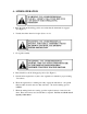
1 – SAFETY PRECAUTIONS THE FOLLOWING PRECAUTIONS ARE SUGGESTED TO HELP PREVENT ACCIDENTS. A CAREFUL OPERATOR IS THE BEST OPERATOR. MOST ACCIDENTS CAN BE AVOIDED BY OBSERVING CERTAIN PRECAUTIONS. READ AND PRACTICE THE FOLLOWING PRECAUTIONS BEFORE OPERATING THIS EQUIPMENT TO HELP PREVENT ACCIDENTS. EQUIPMENT SHOULD BE OPERATED ONLY BY THOSE WHO ARE RESPONSIBLE AND HAVE BEEN PROPERLY INSTRUCTED. Read all operating and maintenance instruction before operating or servicing the mixer.
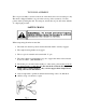
Never charge or fill the unit prior to starting the mixing blades as an overload encountered in starting a loaded unit could damage the engine/motor or drive components. Connect safety chains only as instructed as noted in section 3 of this manual when towing the mixer. Connect only to a hitch, or pintle type coupler. Keep warning, caution and safety instruction labels clean and in good condition. Replace missing, damaged or illegible labels.
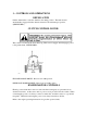
3 – CONTROLS AND OPERATIONS DRUM LATCH Lift the drum latch to rotate the drum into the dump position. The latch should automatically engage when the drum is returned to the mix/transport position. (SEE FIGURE 3) CLUTCH CONTROL LEVER This control is located at the front mixer leg. This control engages and disengages power to the paddle shaft. SEE FIGURE 1. ENGAGE PADDLE DRIVE: Place lever in 2:00 position. DISENGAGE PADDLE DRIVE: Place lever in 12:00 position.
TOW POLE ASSEMBLY The tow pole assembly is located on the front of the mixer and is used for transport only. The mixer is shipped with the tow pole in the stowed position (retracted). Use this position when operating the unit. For transport, extend the tow pole and secure with the “L” shaped pin provided. SAFTEY CHAINS When transporting the mixer ensure that: 1. The drum is in the mix position and that the drum latch is securely engaged. 2. The engine housing latches are engaged. 3.
4 – MIXER OPERATION 1. Place the drum in the mixing position and verify that the drum latch is engaged. (See Figure 3) 2. Visually check the drum for foreign objects or tools. 3. Close grill assembly. 4. Place clutch lever in the disengaged position (See Figure 1). 5. Start the mixer engine/motor (refer to the engine/motor manual for proper starting Procedures. 6.
8. Allow the entire mixture to mix for one (1) full minute. DO NOT DISENGAGE DRIVE CLUTCH LEVER. Release drum latch and rotate the drum to the dump position while the paddles continue to rotate. After the mixture is discharged, return the drum to the operating position and verify engagement of drum latch. EXTENSION CORDS FOR ELECTRIC MOTORS Extension cord must be a 3-wire power plug – approved for outdoor use.
6 – LUBRICATION DRUM SEAL HOUSINGS Drum seal housings are attached to each end of the drum. Each has a grease fitting located at the top, and a vent port on the bottom. It is important to grease this component weekly, more often during heavy use to retain seal efficiency. Use a lithium based grade 2 multi-purpose grease DRUM SHAFT BEARING HANGERS The drum bearing hangers support the drum assembly and provide the pivot point for drum rotation.
ENGINE/MOTOR Refer to the engine/motor operating instructions for all maintenance, lubrication and specifications. 7 – ADJUSTMENT MIXING PADDLES 1. The mixing paddles feature adjustable rubber wipers and steel backing plates. These items are factory preset for appropriate drum clearance. If adjustment is required, proceed as follows: a. loosen wiper hardware and position blade so that even contact is achieved without folding the wiper over when in operation. b.
IDLER/TENSIONER Belt tension is preset at the factory, after approximately 40 hours of operation an adjustment may be necessary to compensate for normal belt stretch. This may be accomplished by adjusting the linkage rod connected to the idler/tensioner pulley bracket. IMPORTANT: Do Not over tension the belts, doing so will prevent the clutch from disengaging power to the paddle shaft. Maintain enough free play in the belts so that they will slip when the clutch is disengaged.
8 – STORAGE For short term storage, clean the mixer and store in a dry location. For long term storage prepare the mixer as follows: 1. Clean the unit thoroughly. 2. Lubricate per instructions outlined in the LUBRICATION section. 3. Refer to the engine/motor instructions for storage instructions. 4. Cover exposed metal surfaces with a thin coat of SAE 30 weight engine oil. 5. Store in a dry location.
GILSON MIXER WARRANTY WARRANTY: This mixer is warranted to the original purchaser only, to be free of defects in material and workmanship under normal use, for one year from purchase date. Cleform Tool Corp. shall without charge, repair or replace parts which are found to be defective. All transportation charges for replacement parts must be borne to the purchaser.
d) A copy of the warranty and service contract information for the above items is furnished with the individual product. 2. All consequential damages, including pickup and delivery of the unit, communication, mileage charges and/or rental of a replacement unit during repairs are not covered under this warranty, nor is any loss of income and/or other loss resulting from the failure of the product to function due to a warranty defect. 3.
HOW TO OBTAIN PARTS AND SERVICE INFORMATION For parts and service information,contact either your local dealer or the Cleform Tool Corp. factory: CLEFORM TOOL CORP. 4343 EASTON ROAD ST.