OPERATIONS MANUAL AND PARTS BOOK 36E55 - 36" 5.5HP 36PE9 - 36" 9HP EDGER 46E9NH - 46" 9HP 46E11 - 46" 11HP Marshalltown, IA Phone 800-888-0127 / 641-753-0127 Fax 800-477-6341 / 641-753-6341 www.marshalltown.
LIMITED WARRANTY Marshalltown Company warrants its products to be free of defects in material or workmanship for the following periods: A. All New Machines and Parts B. All New Gear Boxes 6 Months 2 Years Warranty period begins on first day of use by End User. This first day of use is established by a completed warranty card or a Bill of Sale to the end user. All warranty is based on the following limited warranty terms and conditions. 1.
1A OPERATIONS THE INFORMATION CONTAINED IN THIS MANUAL WAS BASED ON MACHINES IN PRODUCTION AT THE TIME OF PUBLICATION. MARSHALLTOWN COMPANY RESERVES THE RIGHT TO CHANGE ANY PORTION OF THIS MANUAL WITHOUT NOTICE. Information Contained in this Manual: This manual provides information and procedures to safely operate and maintain the Marshalltown Company’s CYCLONE™ Power Trowels.
1A OPERATIONS IMPORTANT REMINDER Fill out your Marshalltown Company warranty card and place it in the mail within 24 hours of delivery. Complete other warranty requirements as specified by the engine manufacturer in their instructions attached to the engine. Your engine is not manufactured by Marshalltown Company, and therefore is not covered under our warranty. Your engine manufacturer should be contacted if you wish to purchase a parts manual or a repair manual for your engine.
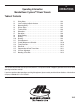
Operating Information Marshalltown Cyclone™ Power Trowels 1A OPERATIONS Table of Contents 1.1 1.2 1.3 1.4 1.5 1.6 1.7 1.8 1.9 1.10 1.11 1.12 1.13 1.14 1.15 1.16 1.17 Safety Notes . . . . . . . . . . . . . . . . . . . . . . . . . . . . . . . . . . . . . . . . . . . . . . . . . Laws Pertaining to Spark Arrestors . . . . . . . . . . . . . . . . . . . . . . . . . . . . . . . Operating Safety . . . . . . . . . . . . . . . . . . . . . . . . . . . . . . . . . . . . . . . . . . . . . Service Safety . . . . .
1A OPERATIONS 1.1 Safety Notes This manual contains NOTES, CAUTIONS, and WARNINGS which must be followed to reduce the possibility of improper service, damage to the equipment, or personal injury. Read and follow all NOTES, CAUTIONS and WARNINGS included in instructions.
1.4 Service Safety 1A OPERATIONS Poorly maintained equipment can become a safety hazard! In order for the equipment to operate safely and properly over a long period of time, periodic maintenance and occasional repairs are necessary. Warning DO NOT attempt to clean or service machine while it is running. Rotating parts can cause servere injury. DO NOT crank a flooded engine with the spark plug removed on gasoline-powered engines. Fuel trapped in the cylinder will squirt out of the spark plug hole.
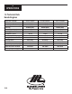
1A OPERATIONS 1.5 Technical Data Honda Engines Engine Make and Model Honda 5.5 GX160 Honda 9.0 GX270 Honda 11.0 GX340 Rated Power - hp (kw) 5.5 (2.9) 9.0 (6.0) 11.0 (8.2) Piston Displacement - cu. in (cc) 9.9 (162) 16.5 (270) 21 (344) BPR6ES (NGK) BPR6ES (NGK) BPR6ES (NGK) Electrode Gap - in. (mm) .029 (.75) .029 (.75) .029 (.75) Operating Speed - RPM 3800 3800 3800 Fuel Capacity - gal. (L) .95 (2.5) 1.4 (5.3) 1.6 (6.0) Fuel Consumption - lb/hph (g/kwh) .50 (310) .51 (313) .
1A OPERATIONS TROWEL 36" 36" EDGER 46” 9HP 46" 11HP Length - in. (mm) 72 (1828) 80 (2032 78 (1981) 78 (1981) Width - in. (mm) 38 (965) 36.5 (927) 48 (1219) 48 (1219) Operating Weight - lbs (kg) 230 (104) 226 (102) 238 (108) 238 (108) Troweling Width - in. (mm) 36 (914) 36.
1A OPERATIONS 1.7 Description The Cyclone™ Power Trowel is a modern high production machine. Finishing rate will vary depending on operator skill and job conditions. The trowel has four finishing blades. The standard duty gearbox is designed to provide exceptional performance low maintenance and trouble free use under the worst conditions. All Cyclone™ Power Trowels are equipped with a safety shutdown switch and a low oil shutdown alert for added job safety and engine protection.
1.10 Steering 1A OPERATIONS Push down on the handle to move the rotor assembly to the right. Pull up on the handle assembly to move the rotor assembly to the left. 1.11 Pitch Adjustment When changing or setting the pitch of the machine be sure that the machine is at a complete stop. On machines equipped with standard pitch, turn the pitch control knob clockwise to increase the pitch and turn it counter-clockwise to decrease the pitch.
1A OPERATIONS 1.12 Periodic Maintenance Schedule The chart below lists basic engine maintenance. Refer to engine manufacturer’s Operation Manual for additional information on engine maintenance. A copy of the engine Operator’s Manual was supplied with the machine when it was shipped.
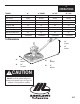
1A OPERATIONS 1.14 Drive Belts E D A D B C Figure 1 Figure 3 Figure 2 To Replace Belts: 1. 2. 3. 4. Remove belt guard (A) by removing the four belt guard mounting bolts (B). See figure 1. Rotate the pulley (C) while pulling the bottom of the belt (D) out. See figure 2. After the belt (D) has cleared the pulley, remove it from the clutch (E). See figure 3. Repeat steps 1 through 3 in reverse order to install the new belt.
1A OPERATIONS 1.16 Lift Lever Adjustment Damage to, or replacement of, a trowel arm can change the adjustment of the lift lever. This can unbalance the trowel arms and cause the trowel to wobble during operation. To operate smoothly, the lift lever on all arms must be adjusted equally. All arms should be adjusted at the same time to ensure that the trowel is balanced correctly. Adjust trowel arms using optional adjusting tool as described below. 1. Block up pressure plate using wooden blocks (b).
2A ASSEMBLY ASSEMBLY INSTRUCTIONS STEP 1: Un-pack the handle assembly(A) and the lower unit from their boxes. Check to make sure no damage was done during shipment. Mount the handle assembly(A) to the gearbox(B) on the lower unit using 4 3/8" nylock nuts(C) that are supplied in a package on the lower unit. C A B Step 1 STEP 2: With the handle mounted to the lower unit, attach the pitch control cable(A) through the yoke arm(B) using the remaining 3/8" nylock nut(C).
3A PARTS 3A-1 LOWER END ASSEMBLY
LOWER END ASSEMBLY (cont’d) ILL. PART # DESCRIPTION QTY. 1 . . . . . . . M037619 . . . . . RING, 36" . . . . . . . . . . . . . 1 . . . . . . . . M037626 . . . . . RING, 46" . . . . . . . . . . . . . 1 2. . . . . . . . M221480 . . . . . LIFTING HOOK . . . . . . . . 1 3. . . . . . . . M018961 . . . . . ENGINE, 5.5 HO . . . . . . . 1 . . . . . . . . M018735 . . . . . ENGINE, 9 HO . . . . . . . . . 1 . . . . . . . . M018967 . . . . . ENGINE, 11 HO . . . . . . . . 1 4. . . . . . . .
3A HANDLE ASSEMBLY PARTS FINE PITCH ILL. PART # 1. . . . . . . . . M037668 . . . . . . . 2. . . . . . . . . M015724 . . . . . . . . . . . . . . . . .M015725 . . . . . . . . . . . . . . . . .M028012 . . . . . . . . . . . . . . . . .M034449 . . . . . . . . . . . . . . . . .M020498 . . . . . . . . . . . . . . . . .M020499 . . . . . . . 3. . . . . . . . . M015739 . . . . . . . 4. . . . . . . . . M015740 . . . . . . . 5. . . . . . . . . M015741 . . . . . . . 6. . . . . . . . . M015743 . . . . . . . 7. . .
PITCH CONTROL ASSEMBLY 3A PARTS POSITIVE PITCH From this view the Chain (11) go around the Sprocket (9) in a clockwise motion to operate correctly. ILL. 1. . . . . . . . . . . . 2. . . . . . . . . . . . 3. . . . . . . . . . . . 4. . . . . . . . . . . . 5. . . . . . . . . . . . 6. . . . . . . . . . . . 7. . . . . . . . . . . . 8. . . . . . . . . . . . 9. . . . . . . . . . . . 10. . . . . . . . . . . 11. . . . . . . . . . . 12. . . . . . . . . . . ............ 13. . . . . . . . . . . 14. . . . . . . . .
3A PARTS 3A-5 GEARBOX ASSEMBLY
GEARBOX ASSEMBLY (cont’d) 3A PARTS ILL. PART # DESCRIPTION QTY. 1. . . . . . . . . . . . . . . M015205 . . . . . . . . . SCREW, 5/16-18 x 1 . . . . . . . . . . . . . . . . . . . . . . . . . . . . . . . . 8 2. . . . . . . . . . . . . . . M015209 . . . . . . . . . VALVE, 1/8 NPT-27 RELIEF . . . . . . . . . . . . . . . . . . . . . . . . . . 1 3. . . . . . . . . . . . . . . M015208 . . . . . . . . . COVER, GEARBOX MACHINED . . . . . . . . . . . . . . . . . . . . . . 1 4. . . . . . . . . . . . . . .
3A PARTS KILL SWITCH ASSEMBLY ILL. PART # DESCRIPTION QTY. 1. . . . . . . . . . . . . . . M013370 . . . . . . . . . SCREW, 10-32 x 3/8 SLOTTED . . . . . . . . . . . . . . . . . . . . . . . 2 2. . . . . . . . . . . . . . . M018512 . . . . . . . . . CONDUIT, RD PVC 1/4” SMOOTH . . . . . . . . . . . . . . . . . . . . . 6.6 ft. 3. . . . . . . . . . . . . . . M018624 . . . . . . . . . SCREW, SLT 8-32 x 1 . . . . . . . . . . . . . . . . . . . . . . . . . . . . . . . 1 4. . . . . . . . . . . . . . .
3A SPEED KITS PARTS LOW SPEED KITS 6 3 3 6 5 HP 1 8 & 11 HP 2 2 1 4 4 5 5 ILL. PART # DESCRIPTION QTY. 1. . . . . . . . . . . . . . . M027242 . . . . . . . . . BELT GUARD (9 & 11 HP) . . . . . . . . . . . . . . . . . . . . . . . . . . . 1 . . . . . . . . . . . . . . . M032696 . . . . . . . . . BELT GUARD (5.5 HP) . . . . . . . . . . . . . . . . . . . . . . . . . . . . . . 1 2. . . . . . . . . . . . . . . M029102 . . . . . . . . . PULLEY, BK90 . . . . . . . . . . . . . . . . . . . . . . . .
3A PARTS OPTIONAL ACCESSORIES PAN36-4C PAN36-4CE PAN46-4C SPIDER PULLER M035688 ALIGNMENT JIG M016863 10 POUND WEIGHT M010640 ROLLING TRANSPORT SYSTEM M040349 3A-9