Marshall Electronics Model No.
This page intentionally left blank 2
Table of Contents Installation and Initial Setup ------------------------------------------------------------------------------------------------------5 Top and Front Panel Features ----------------------------------------------------------------------------------------------------6 Rear Panel Features-----------------------------------------------------------------------------------------------------------------7 Compatible Input Formats----------------------------------------------------------------------
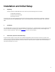
Installation and Initial Setup ■ Unpacking Carefully unpack the V-R653-IMD-3GTE monitor and verify that the following items are included: • V-R653-IMD-3GTE Monitor • V-PS12-5V-1 DC Power Supply • Operating Instructions Inspect the unit for any physical damage that may have occurred during shipping. Should there be any damage, immediately contact Marshall Electronics at (800) 800-6608. If you are not located within the continental United States, call +1 (310) 3330606.
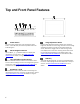
Top and Front Panel Features Power Button Turn the monitor panel off or on by pressing the power button. In the ON state, the LED on the power button will illuminate green. Menu Navigation Buttons Use the Menu, ↑, ↓, and Select buttons to display and navigate the on-screen menu. See MAIN MENU AND NAVIGATION for details on using the Menu. User-Definable Function Buttons Two user-definable function buttons can be used for direct access to various settings. Functions are assigned using the onscreen menu.
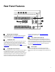
Rear Panel Features 3G-SDI Input and Output The V-R653-IMD-3GTE has one HD-SDI input and one active loop-through output. See Compatible Input Formats for details on accepted formats. Headphone Jack The 1/8” jack on the back of the monitor takes two channels of embedded SDI audio and provides a Headphone audio signal. Volume can be adjusted via the RotoMenu knob or in the Audio Configuration submenu. See the Audio Configuration section for instructions on how to select the two audio channels.
Compatible Input Formats SDI/HDSDI Inputs 525i/ 59.94, 625i/ 50 720p/ 23.98, 24, 25, 29.97, 30, 50, 59.94, 60 1080p/ 23.98, 23.98sF, 24, 24sF, 25, 29.97, 30 1035i/ 59.94, 60 1080i/ 50, 59.94, 60 3G-SDI Inputs 3G – Level A and Level B YCbCr, YCbCr+A, RGB, RGB+A 1080p/ 60, 59.94, 50 1080p/ 30, 29.97, 25, 24, 23.98, 30sF, 29.97sF, 25sF, 24sF, 23.98sF 1080i/ 60, 59.
MAIN MENU AND NAVIGATION Access and navigate the main menu using the 4 menu buttons or the RotoMenu™ knob: Main Menu Using the menu buttons • • • • Press the MENU button to enter the main menu. Use the and buttons to scroll through the main menu or each submenu. Press the SELECT button to enter a submenu or choose a setting. Press the MENU button to exit the main menu, or return to the main menu from a submenu. Using the RotoMenu knob • • • Press the RotoMenu™ knob to enter the main menu.
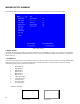
MARKER SETUP SUBMENU Use the Marker Setup submenu to select various types of markers and settings in 4:3, 16:9, or Full Screen mode. Marker Setup Submenu ■ Marker Enable The Marker Enable setting turns 16:9 or 4:3 screen markers On or Off. By default, this setting is On. If you turn the setting OFF, the markers are automatically turned ON the next time you initiate a Screen Marker through a Function Button or through the Marker submenu.
■ 4:3 Markers Use this setting to superimpose one of 5 markers on the screen when in 4:3 mode. This setting is disabled when the aspect ratio is set to 16:9 or Full Screen, and when Pixel-to-Pixel mode is enabled.
VIDEO CONFIGURATION SUBMENU Use the Video Configuration submenu to select various video settings such as monochrome mode or blue-only mode. Video Configuration Submenu ■ Monochrome Mode Use this setting to enable monochrome mode. Only the luminance of the image will be displayed as a grayscale picture. ■ Blue-Only Mode Use this setting to enable Blue-Only mode. This mode displays only the blue color component of the image, switching off the red and green components.
■ Pixel-to-Pixel Mode Use this setting to enable Pixel-to-Pixel mode. This mode bypasses the monitor’s internal scaling function and displays images in their native resolution and aspect ratio, with a one-to-one mapping of incoming image pixels to screen pixels: • For incoming formats smaller than the native resolution of the screen (or selected aspect ratio), the image will be displayed in the center of the screen using only the necessary LCD pixels.
00:00:00:00 00:00:00:00 00:00:00:00 IMD Text IMD Text Scaled 4:3 4:3 00:00:00:00 00:00:00:00 IMD Text Scaled 16:9 ■ IMD Text 16:9 Curtain Color Use this setting to choose the default color displayed on the screen when no video input is present. Available colors are blue, red, green, white, and black. ■ Sharpness Sharpness is a type of edge enhancement that can be applied to incoming video signals. Use this setting to increase or decrease the amount of enhancement applied to the image.
COLOR CONFIGURATION SUBMENU Use the Color Configuration submenu to adjust the color temperature of the display. Color Configuration Submenu ■ Ctemp/Gamma Use this setting to choose one of three color temperature / gamma presets: • • • • ■ D55 (5500K) D65 (6500K) D93 (9300K) Linear (No gamma applied) Red, Green, and Blue Offset Use the offset controls for red, green, and blue to adjust the color temperature of the display.
■ Delete Gamma Use this setting to Delete any custom Gamma tables that have been loaded to the monitor’s memory. Note: Once a setting is Deleted, it cannot be recovered from the monitor. SYSTEM CONFIGURATION SUBMENU Use the System Configuration submenu to control various system parameters. System Configuration Submenu ■ Gray Levels Use the Gray Levels menu option to view 256 levels of flat field gray. This feature is useful for color temperature comparison and calibration.
• • • • ■ Pixel to Pixel Ctemp/Gamma Blue Only Monochrome Enable/disable Pixel-to-Pixel mode Rotate amongst color temperature settings Enable/disable Blue Only mode Enable/disable Monochrome mode Save Defaults Use this setting to save the current values of the Color, Brightness, and Contrast controls as the default values. The defaults can then be accessed by pushing the knob twice.
DEINTERLACER SUBMENU Use the Deinterlacer submenu to control the type of deinterlacing performed on interlaced input signals. System Configuration Submenu ■ Deinterlacer Mode Use the Deinterlacer Mode option to set the type of deinterlacing algorithm used: • In Auto mode, the deinterlacer defaults to Motion Adaptive mode (see below), but uses Film Mode (see below) whenever a film cadence is detected. This is the optimum deinterlacing mode for best picture quality and should be used whenever possible.
Use the Film Mode setting to limit the film mode detection to a specific cadence. • • • ■ Auto Deinterlacer automatically identifies the film cadence 2:2 only Deinterlacer only recognizes content originating in 25fps, and uses 2:2 film mode. 24fps content is ignored. 3:2 only Deinterlacer only recognizes content originating in 24fps, and uses 3:2 film mode. 25fps content is ignored. Film Indicator Use the Film Indicator setting to enable or disable the film mode detection icon.
■ IMD State Use this setting to turn the IMD text display on or off. This setting affects both fixed string IMD text and remote IMD text commands (see IMD Configuration Submenu for details). ■ Status Display Use this setting to enable or disable status display. When enabled, the current video input standard is displayed on the top left of the screen. When disabled, status is only displayed for 2 seconds when the monitor is powered on, when an input is applied, or when the input video standard changes.
■ OSD Tally Use this setting to choose how tally is displayed on the screen. The available OSD Tally options depend on the Tally Source selected in the IMD Configuration submenu (see page 22). When the Tally Source is set to Standard (contact closure), OSD Tally can be set to Off, RGY, RG, or GR: • Off On-screen tally is disabled • RGY Red, yellow, or green tally signals are indicated at both the bottom left and bottom right corners of the screen.
When the Tally Source is set to TSL/MEI 422, OSD Tally can be set to Off or IMD: • Off On-screen tally is disabled • IMD Red, yellow, and green tally is displayed according the protocol commands. Green, red, and yellow colors are shown individually on either the bottom left or right of the screen. ■ LED Tally Use this setting to enable or disable the LED Tally.
CC CONFIGURATION SUBMENU Use the CC Configuration submenu to select the type of captioning stream you would like to decode. IMD Configuration Submenu ■ CC Mode The IMD-3G monitor series provides support for two types of Closed Captioning Modes: 608 and 708 (608 Comp.). Use this section to choose which type of stream you would like to decode. ■ 608 Service The EIA-608 caption protocol defines four channels of caption information and four channels of text information.
AUDIO CONFIGURATION SUBMENU Use the Audio Configuration submenu to ■ Audio Bars The IMD-3G monitor series provides audio level indicators for SDI streams with embedded audio. Support for up to 16 channels (labeled as Groups 1, 2, 3 and 4) is provided.
■ Mute The Mute function disables audio output from Headphone output on the IMD 3G monitor. This will NOT control the Line Out level of the monitor, only the Headphone output. ■ Volume The Volume control determines the output level for the Headphone out on the IMD-3G monitor. This will NOT control the Line Out level of the monitor, only the Headphone output. ■ Audio Delay The Audio Delay function applies a delay to the Audio Metering and audio output.
■ IMD Protocol Use the IMD Protocol menu option to choose the protocol with which the V-R653-IMD-3GTE receives remote commands. Currently, four protocols are available. Contact Marshall Electronics for the latest protocol compatibility. Image Video Use the Image Video protocol setting when controlling the IMD from an Image Video tally controller (e.g. TSI-1000) or other controlling device which utilizes the Image Video protocol.
■ IMD Fixed Color Use this setting to choose the color of the IMD Fixed String text (see below). Available colors are red, green, and yellow. This setting does not affect text color when using IMD text via the Image Video or TSL v4.0 protocols (text color is set via the protocols). ■ IMD Fixed String Use this setting to display static IMD text on the screen. This setting is used to enter IMD text locally, when a serial protocol is not used for remote control.
SERVICE SUBMENU ■ Overview The Service submenu displays the firmware versions of the monitor. Additionally, the status of the serial interface, for troubleshooting or debugging purposes, can be shown on the screen by highlighting and selecting the Show Statistics text in the Service Submenu. Contact Marshall Electronics for further information.
Specifications ■ PANEL Screen Size Display Area (h x v) Pixels Viewing Angle(h x v) Brightness Contrast Ratio ■ 6.5” Diagonal 132.096 x 99.072 mm 1042 x RGB x 768 160° x 140° 650 cd/m2 500:1 ■ TALLY/GPI HARDWARE INTERFACE (HD-15) Activation requires contact closure of pin to ground on the HD-15 connector: VIDEO INPUT/OUTPUT HD-SDI Input / Output ■ CONNECTORS 3G-SDI Video Input 1 x BNC Female (75 Ω) 3G-SDI Video Output (Active Loop-Through) 1 x BNC Female (75 Ω) ■ Headphone Out 1/8” (3.
Dimensions 30
Maintenance ■ Screen Cleaning Periodically clean the screen surface using ammonia-free cleaning wipes (Marshall Part No. V-HWP-K). A clean micro-fiber cloth can also be used using only non-abrasive and ammonia-free cleaning agents. Do not use paper towels. Paper towel fibers are coarse and may scratch the surface of the polycarbonate faceplate or leave streaks on the surface. Antistatic and fingerprint resistant cleaning agents are recommended.
Marshall Electronics, Inc. 1910 East Maple Ave. El Segundo, CA 90245 Tel: (800) 800-6608 / (310) 333-0606 • Fax: 310-333-0688 www.LCDRacks.com • sales@lcdracks.