
Operating instructions


5
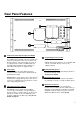
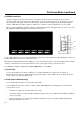
Rear Panel Features
Component and Composite Input and Output
The V-MD171X has HD/SD component (YPbPr) and
composite analog input. There is as an active loop-
through output for each analog input. See page 10
for supported video formats. The BNC inputs are
internally terminated with 75 ohms. Outputs are
active ONLY when power is supplied to unit.
Power Input
Connect 12VDC to the 4-pin XLR power input
connector. Power should only be supplied from the
included power supply.
IMPORTANT: If using a power source other than the
included power supply, damage may result. Please
use the pin out diagram in the Specifications section
of these Operating Instructions.
Tally Input Connector (HD-15)
The LED tally can be activated via the HD-15
connector by connecting the corresponding pin to
ground. A variety of external devices can be used to
perform the contact closure. No additional power
should be supplied to the HD-15 port. See pin-out
details on page 22.
Programming Connector CN1*
For Factory Use ONLY.
*NOTE* although this appears to be a standard USB
connector, It is NOT. Do not connect to any
computer directly.
Desktop Mounting Holes
These holes are used when attaching the monitor to
the optional desktop stand.
See page 5 for details
VESA 75mm Hole Pattern
VESA-standard 75 mm hole-pattern is provided to
accommodate a variety of custom mounting options.
Input Slots, S1 and S2
The V-MD171X has 2 slots for optional input
modules. These modules allow for a wide variety of
input types and configurations. Modules are COLD
swappable and must only be inserted or removed
ONLY when Main Power is UPGLUGGED.