
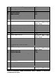
Technical data


CHAP-04.10 ELECTRICAL POWER DISTRIBUTION, DRIVES, CONTROL &
ILLUMINATION ELECTRICAL
Page 49 of 50
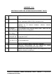
ANNEXURE-E04
SL.
NO.
DESCRIPTION
1.
The HT and control cable from HTSS to the respective technological
package will be routed through covered structural overhead cable gallery
only.
2.
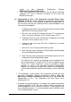
All circuit breakers used for 6.6 KV and 11 KV unearthed system should be
1. VCB’s
2. They will be horizontal isolation type, trolley mounted and ground
operated (non cassette type)
3. The jaw contacts (female) will be mounted on the breaker and will be
drawout along with the breaker.
4. The male contact will be of flat type with mounting on bus side
5. Type tests pertaining to BIL requirements (7.2/28/60KV for 6.6 KV and
12/35/75 KV for 11 KV) will be witnessed by EMPLOYER.
6. Minimum panel width will be 800 mm.
3.
Continuous current of Variable speed AC drives will be 150% of motor full
load rated current at continuous duty operation.
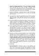
4.
Insulation level for MCC & MCP: One minute power frequencies withstand
voltage will be 1500V for control circuit.
5.
Contact rating for Push Button will be
AC15, 6A at 230V
DC13 ,4A at 230 V
6.
MCB short circuit rating capacity will not be less than 10 KA at 0.8 power
factor
7.
LT Switchboard Incomer & Bus-coupler Circuit Breaker ratings will be 2000A
for 1000KVA transformer
8.
Control terminal block will be ELMEX type suitable for terminating 2 cores of
2.5 sq mm wire.
9.
Terminal type
Power terminal: Stud type- with maximum 2 connections on one terminal.
Control terminal for CT: Disconnecting type
ANNEXURE-E05
SL.
DESCRIPTION