
Technical information

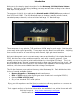

STEP 5: Installing the filter caps (Part 2)
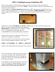
Part 2 of the filter caps installation is mounting them on the chassis with the necessary ground lugs.
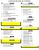
Locate (12) #6 – 3/8” machine screws and Nyloc nuts, also (5) 2 HOLE GROUND LUGS. Install (6)
filter caps in the positions shown using this hardware sequence:
SCREW – CAN CLAMP – CHASSIS – (GROUND LUG) – NUT
Reference the detailed pictures below for correct terminal orientation and which screws require a
ground lug. Tighten using a Philips screwdriver and 5/16” nut driver.
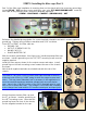
From LEFT to RIGHT, the filter caps are:
• PREAMP CAP
• OUTPUT SCREENS CAPS (2)
• MAINS CAPS (2)
• PHASE INVERTER CAP
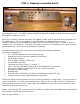
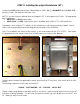
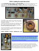
With the chassis upside-down, front facing you, install the preamp filter cap
as shown. Install a ground lug on the TOP, LEFT mounting screw near the
negative terminal.
Install (4) filter caps as shown for the output screens and mains. Install
ground lugs on the both mounting screws nearest the rear of the chassis,
as shown.
Note that all negative terminals are oriented towards the rear of the
chassis.
TECH NOTE: Two 50uf x 50uf @ 500V filter caps are wired in series to
achieve a total of 50uf @ 1000V rating for both the output screens and
mains. This may seem redundant, but is necessary in this application to
meet the requisite maximum operating voltage times two safe design
spec. Later in the JCM 800 version of the 2203, Marshall opted to omit
two of four of these filter caps. This change is circa 1985 and correlates
to the change from hand-wired to PC board mounted pots and input jacks.
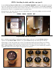
Mount the phase inverter filter cap near
the PT, as shown. Install a ground lug on
the LEFT mounting screw. Note that this
ground lug faces the front of the chassis,
not the negative terminal on the cap.