
Technical information


STEP 3: Installing the output transformer (OT)
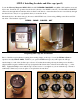
Locate the C1998 output transformer (abbreviated as “OT”), (2) ½” GROMMETS and (4) #10 –3/8”
machine screws, flat washers and Nyloc nuts.
NOTE: if you are using an optional Mercury Magnetics OT, it will replace the C1998. The appropriate
part numbers are:
• MMO-100 for EL34 output tubes
• MMO-100M for 6550 output tubes (also compatible with KT88, KT77, 5881 and 6L6’s)
Fortunately, each of these OT’s adheres to the original wire color scheme used by Dagnall. But for
clarity, the corresponding transformer diagrams are located in the APPENDIX.
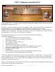
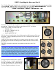
The OT is installed in the center of the chassis, in the same manner as the PT in STEP 2. First install
(2) grommets into the chassis holes, then route the wires according to the diagram.
Feed the wires through the appropriate chassis holes until the OT sits flush, then secure with (4) #10
screws.
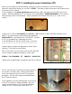
The hardware sequence is the same as for the PT:
SCREW – FLAT WASHER – OT – CHASSIS – NYLOC NUT
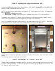
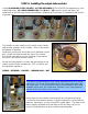
Tighten using a large Philips screwdriver and 3/8” nut driver. Apply masking tape to the top of the OT
to protect it during assembly. You will now find that the chassis can rest upside-down on the PT and
OT, making it easy to work inside.