
Technical information


STEP 2: Installing the power transformer (PT)
When you are ready to start assembling, place the chassis on the bench with the front (pots,
switches, input jacks) facing you, as seen in STEP 1. All steps in these instructions will reference this
as the front of the chassis.
In this orientation, the power transformer (abbreviated as “PT”) will mount on the LEFT end of the
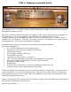
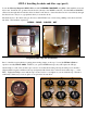
chassis. Before installing the PT, you need to first install (4) ½” RUBBER GROMMETS in the chassis
holes through which wires will pass. Simply squeeze these in place into the (4) ½” holes on the
chassis.
GROMMETS IN PLACE
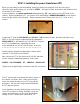
Locate the PT (part # 1203-80-MS) and (4) #10 – 3/8” machine screws, washers and Nyloc nuts.
NOTE: if you are using the optional Mercury Magnetics
MP100-460 PT, it will replace the 1203-80-MS. Prepare
the PT for installation by separating the wires
to be distributed into the (4) chassis holes, as shown.
>>>>>>>>>>>>>>>>>>>>>>>>>
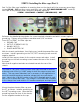
Feed the wires through the appropriate chassis holes
until the PT sits flush on the chassis.
Now secure the PT to the chassis with (4) #10 machine
screws using the hardware sequence shown here:
SCREW – FLAT WASHER – PT – CHASSIS – NYLOC NUT
Tighten with a large Philips screwdriver and 3/8” nut driver.
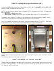
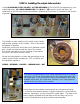
The PT should now be mounted securely in place on
the chassis, as shown here. Make sure that the
wires are routed directly from the PT through the
grommets. Excess wire can get pinched between
the PT and the chassis.
Once installed, put some masking tape over the top
of the PT to protect it during assembly, since the
chassis will spend most of it’s time upside-down,
resting on the PT and output transformer “OT”.