
Technical information

TESTING SECTION: PART 5
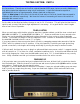
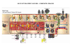
With all the tube sockets tested and receiving the correct voltage on each pin, you can install the
output tubes. Once in place, turn the STANDBY switch to OFF and the POWER switch to ON.
Check to see that the output tubes warm up and start to glow. They will be biased very cold at this
point. But before we dial the bias in, we need to determine the correct idle current to set them at.
Thanks to Ohm’s Law and the 1Ω resistors installed on the output tube sockets this involves just a
little simple math. Here’s the formula:
I = (W * .7) / V
In our formula I represents current flowing through the tube at idle. W represents the dissipation
rating of the tube in watts. We multiply this maximum rating by .7 to calculate a safe rating of 70%
of the max. V represents the B+ voltage in the amp, measured at PIN 3 of the output tube sockets.
Since W and V are fixed values, we will adjust the bias voltage to achieve our calculated value of I.
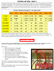
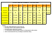
NOTE: if you are using EL34’s the value of W is 25 watts, for 6550’s W is 30 watts.
Let’s insert the values into our equation to solve for I:
EL34’s: I = (25 * .7) / 485V = 17.5 / 485V = .036mA
In a Class A/B, push-pull power amp using EL34’s and a B+ of 485V we should set the idle current
for 36mA.
6550’s: I = (30 * .7) / 485V = 21 / 485V = .043mA
In a Class A/B, push-pull power amp using 6550’s and a B+ of 485V we should set the idle current
for 43mA.
HOW TO SET THE BIAS
Now we know our target value, here’s how to adjust the bias voltage for the correct idle current:
• Plug in a speaker or suitable load
• Power the amp ON
• Allow a short time to warm up and turn STANDBY to ON
• Set your meter to millivolts (mV)
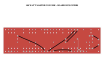
• Ground the negative meter lead in the cage nut hole
• Carefully measure voltage in mV at PIN 1 of V4
• Use a small screwdriver to adjust the bias pot clockwise
• Re-check the reading at PIN 1
• Continue this process until you have
dialed in the desired voltage
When you have the correct reading on V4,
measure mV on PIN 1 of V5, V6 and V7.
They should all measure approx the same as
V4. But will vary slightly depending on how
closely matched your output tube set is.
You can adjust the bias so each of the output
tubes are in the correct range.
CAUTION! HIGH VOLTAGE