
Technical information

TESTING SECTION: PART 4
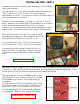
Assuming all has gone well to this point, with your meter still set for DC 500V measure both terminals
of the HT fuse holder. Each should read the same high voltage you found at the positive terminal of
the diode arrangement. If you do not, power off and check the 1 amp fuse. If it does, proceed testing
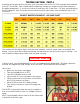
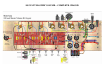
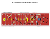
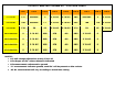
for DC voltage on each of the tube sockets referencing the chart below, also included full size in the
APPENDIX.
The readings will be slightly higher than the chart indicates, until the output tubes are installed and
biased. Just see that they scale proportionally and that each pin has the correct type of voltage. You
can’t install the output tubes unless each pin reads correctly.
CAUTION! 500V DC
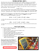
If all tests well, turn the POWER switch to OFF and unplug the AC power cord. The filter capacitors
will now be charged with high voltage, which we MUST DRAIN BEFORE PROCEEDING!
Here’s how:
• Make sure the amp is unplugged
• Turn the POWER switch to OFF
• Turn the STANDBY switch to ON
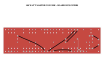
• Clip one end of a short clip lead to the chassis
• Clip the other end to the junction of the 100KΩ
and .022uf terminal, as shown
• Allow 60-90 seconds for voltage to drain
• Test with your meter to ensure all voltage has
drained
This MUST be done each time the amp is powered on.
And you should ALWAYS check for voltage with your
meter.
NOTE: the STANDBY switch must be in the ON position
to drain all of the filter caps.