
Technical information

TESTING SECTION: PART 3
Assuming there were no fireworks upon powering on, you can begin
taking measurements.
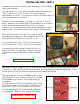
Set your meter to AC volts, with the negative lead grounded on the
chassis, and test V1 pins 4, 5 and 9. You should measure
approximately 3.15V AC. It is common for this to run slightly high, as
seen here measured at 3.24V AC.
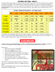
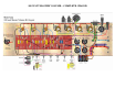
Measure for the same reading on V2 and V3. Also V4 - V7, pins 2
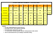
and 8. Reference the voltage chart in the APPENDIX for an overview
of tube and terminals that should have 3.15V AC present.
If all test well, you know that each tube will be supplied the correct
heater current. You should see the 12AX7 preamp tubes glowing.
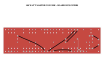
Next, set your meter to DC volts 100V range or higher
and measure for negative DC bias voltage on each of the
5.6kΩ grid resistors attached to PIN 5 of V4 –V7.
You should measure up to –50V DC on each resistor if
you are using EL34’s, up to –65V DC for 6550 specs.
It is essential that this voltage is present on PIN 5 of
output each tube. To apply high voltage to the tubes
without bias voltage would almost certainly damage
them.
CAUTION! UP TO 100V DC
With heater and bias voltages correct, it’s time to throw the STANDBY switch and apply high voltage
to the circuit. With only the preamp tubes installed, the high voltage will read somewhat high. This is
normal and it will level off when the output tubes are installed and biased.
Without further ado, turn the STANDBY switch to ON.
High voltage AC is now traveling from the PT, through
the STANDBY switch and on to the diode bridge for
rectification.
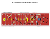
Set your meter to AC 500V and measure approx 180V
AC at the terminals on the far RIGHT of the board, as
shown here. Next, set your meter to DC 500V and
measure approx 480V DC at the terminal marked “+”
on the diagram. Slightly higher readings are normal.
CAUTION! 500V DC