
Technical information
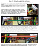
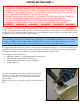


Step 33: Installing the IEC socket and mains fuse.
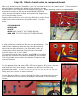
Locate the IEC AC SOCKET, (1) FUSE HOLDER, (2) #6 3/8” screw and Nyloc nuts, (10”) ORANGE
wire, (14”) BLACK wire and (6”) GREEN wire.
Install the IEC socket on the chassis using #6 screws and Nyloc
nuts. The hardware sequence is:
SCREW – SOCKET – CHASSIS – NUT
Tighten with Philips screwdriver and 3/8” nut driver.
Install the MAINS fuse holder on the chassis and tighten in place
with a 14mm wrench or pliers. Do not over-tighten.
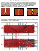
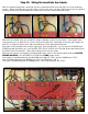
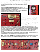
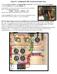
Referencing the diagram, connect a 6” GREEN wire to the lower terminal of the IEC socket (indicated
as “E” for Earth). Route this to the open ground lug on the far mounting screw of the phase inverter
filter cap. It is important that the main AC ground attaches to the chassis with it’s own ground lug.
Wire a 10” ORANGE wire from the neutral terminal of the IEC socket (indicated with an “N”) to the
copper colored terminal of the POWER switch (indicated on the switch as “12”).
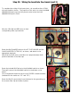
Wire a 10” BLACK wire from the LEFT terminal of the mains fuse holder to the POWER switch terminal
indicated as “25”. And finally, wire a 4” BLACK wire from the HOT terminal of the IEC socket
(indicated with an “L” for Live) to the RIGHT terminal of the mains fuse holder.