
Technical information
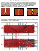


Step 32: Loading the component board!
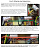
With the board fully wired into the chassis, the fun part can finally begin! Install the board securing
nuts and tighten with a ¼” nut driver. Be sure no wires under the board are pinched between the
board and the mounting screws. This is fairly common and is a pain to
troubleshoot.
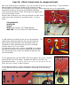
Refer to the BOARD COMPONENTS diagram in the APPENDIX for
component location and values, noting and changes specific to your build
i.e. tweaked circuit values, or using 6550 tubes.
I suggest installing the bias pot first, so there is room to maneuver the
soldering iron in tight while soldering to the terminals.
Identify resistors by color code and type before
soldering in place, values are listed in the Bill of
Materials and a RESISTOR and CAPACITOR
CODE CHART is included in the APPENDIX.
You can double-check values with your meter.
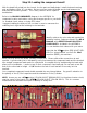
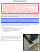
Note that the 2.7kΩ resistor (RED-VIOLET-RED-
GOLD) is “piggy-backed” on the SoZo .68uf
capacitor (684K), pictured here.
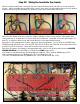
Work your way across the board, installing components. Ensure solid solder connections at each
terminal. A good solder joint is indicated by even flow between the component leads and the terminal.
Nice straight component leads make for a tidy build. Accomplish this by straightening the leads with
pliers prior to installation. I prefer to test fit each component, then bend and cut one lead, re-test fit
and cut the other lead to length. A 1/8” bend on the end of each lead will fit securely into the
terminal.
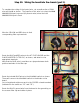
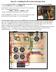
Your completed component board should resemble the one pictured below. Pay specific attention to
the polarity of the (2) 10uf capacitors and the orientation of the (5) diodes.
NOTE: Assure you use a 470Ω resistor (YELLOW-VIOLET-BROWN-GOLD) in the phase inverter circuit,
near the center of the board, not a 470KΩ (YELLOW-VIOLET-YELLOW-GOLD). This is a common
mistake and will decrease the output of the amp to nearly zero.