
Technical information
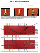


Step 31: Wiring the output tube grid wires.
The final board wires to be attached are the output tube grid wires (ORANGE, GREEN). These can be
tricky to install since the grid resistors are flying off the output tube
sockets.
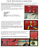
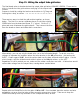
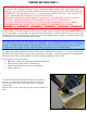
Prepare to install by cutting the lead on each resistor to ½” long and
forming into a loop, as shown. >>>>>>>>>>>>>>>>>
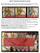
There are two ways to chain the grid resistor together, as shown
below. The first is to use two separate pieces of wire (the existing
GREEN wire from the board and a new 2 ½” piece). Cut the 2 ½”
piece and route it between the grid resistors. Then connect the wire
from the board as shown and solder both connections.
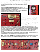
Alternatively, you can use only the board wire, cut to the full needed length. To do this, use wire
strippers to separate the insulation where the wire attaches to the V5 grid resistor - pictured on the
RIGHT. Create a gap of 1/8”. Hook the resistor lead over the bare wire and solder in place. Cut the
wire to length, strip the insulation and solder in place on the V4 grid resistor, on the LEFT.
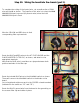
Regardless of which method you use, make sure the solder connections are solid. A failure here would
remove bias voltage from the output tube, causing almost certain failure.
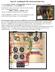
Repeat with the ORANGE wire for the grids of V6 and V7. Once installed, bend the resistor and wire
assemblies out away from the tube sockets enough to prevent any shorts. Take care to keep the
GREEN wires away from any terminals on the component board, as well.