
Technical information


Step 30: Wiring the board into the chassis (part 2).
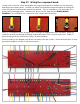
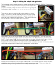
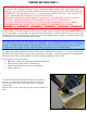
To complete the wiring of the inputs jacks, cut a small section of PINK
wire and install as shown. The purpose of this wire is to short the HIGH
SENSITIVITY input to ground (to prevent noise) when the LOW
SENSITIVITY input is used.
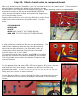
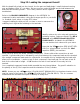
Wire the YELLOW and RED wires to their
corresponding filter cap terminals.
Route the BLUE and RED wires to the HT FUSE HOLDER and the
PHASE INVERTER FILTER CAP, as shown, and attach to the
appropriate terminals.
Note that the BLUE wire is used also as a jumper between both
positive terminals of the filter cap.
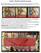
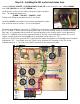
Route the twisted BLUE wires to the STANDBY switch as shown.
These will connect the STANDBY switch to the diodes on the
board.
Cut to length and solder one each to the COPPER colored terminals
(indicated on the switch as “12” and “25”).
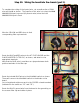
Route the BLACK ground wire from the board to the ground lug on
the screens filter cap and solder in place.