
Technical information
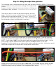


Step 29: Wiring the board into the chassis.
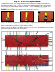
With the under-board wires connected, flip the component board over and place it on the mounting
screws. Before installing the mounting nuts, stretch each wire out and organize them into the general
locations where they will be attached. Make sure none are tucked under the board.
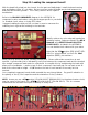
With all of the board wires accounted for, begin soldering in place in the chassis. Wire length and
routing are key to an amp which is free of hum and extra noise, especially in the first gain stages (V1
and V2), so keep the wires short and routed directly to the appropriate terminal.
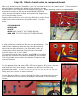
Wire each of the preamp tube sockets, input jack, pots and grounds. Do not wire the ORANGE and
GREEN twisted grid wires yet. Nor the RED, RED, BLUE, BLACK and YELLOW wires that extend from
the RIGHT end of the board. These will be attached in the next steps.
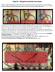
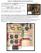
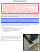
With all of the wires connected to the appropriate pots, refer to the picture below and the CHASSIS
WIRING DIAGRAM in the APPENDIX to install three PINK jumper wires.
One jumper is installed between the MASTER VOLUME pot, PIN 1 and the TREBLE pot, PIN 2.
One is installed between the TREBLE pot, PIN 3 and BASS pot, PIN 2.
The third is installed between the MIDDLE pot, PIN 1 and the BASS pot, PIN 3.