
Technical information
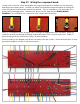
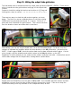


Step 28: Attach chassis wires to component board.
With your board wired for installation, you can now attach each of the chassis wires. These should be
attached before installing the board on the mounting screws.
Sit the board in the chassis with the bottom facing you. Begin attaching wires to the appropriate
terminals according to the picture and WIRING DIAGRAM.
Leave enough extra wire to allow the board to be flipped over,
on to the mounting screws.
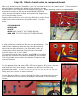
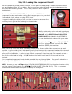
Ensure solid connections, as it will very difficult to re-flow these
solder joints after the board is mounted in place. Connect
these:
• YELLOW/BLACK
• WHITE/RED
• VIOLET
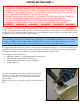
• BLUE BIAS FROM PT (PICTURED BELOW)
• RED, RED TO FILTER CAN (PICTURED BELOW)
A solid solder joint should look like the one pictured here. The
solder flows seamlessly between the wires and terminal.
Note that the entire terminal is not filled with solder, as
components will be attached from the top of the board.
Only the lower 1/8” or so is filled.
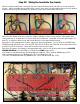
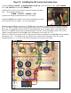
For connections with only one wire, strip 5/16” of insulation
and fold the conductor over before installing in the terminal.
This will provide more contact and a better fit between the
wire and terminal.
For the preamp filter cap wires (RED, RED) twist approx. 5” of wire, strip the
ends and form into hook shapes. Squeeze into place on the filter cap
terminals and solder. >>>>>>>>>>>>>>>>>>>>>>>>>
Either wire can connect to either terminal.
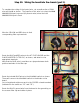
For the bias wire (below), route it through the hole in the board and connect
to the terminal when you flip the board down and install on the mounting
screws.