
Technical information
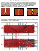


Step 27: Wiring the component board.
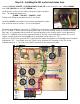
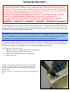
Locate each of the wire colors and prepare the component board for installation in the chassis by
attaching the necessary wires. Another cue taken from Marshall component boards is running the
wires through the board and then around the terminal. This isn’t mandatory, but does make for a
great looking finished product. Reference the photos on this page and the BOARD WIRING
DIAGRAM in the APPENDIX for correct wire color, length and connections.
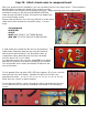
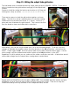
Strip ¼” of insulation from a wire and route it through the appropriate hole in he board. Wrap the
conductor around the terminal and lightly squeeze with pliers into a uniform semi-circle. Solder in
place ensuring that the solder flows evenly, as pictured above.
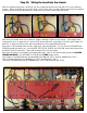
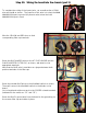
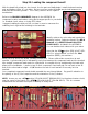
Work according to the diagram until all the necessary wires are in place. Note that three pairs of wires
get twisted together, as seen in the bottom photo.