
Technical information
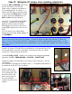
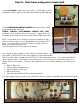

Step 26: Installing buss wire on the board.
Locate the COMPONENT BOARD, (3’) 22g BUSS wire, and (2’) 18g SLEEVING.
Our point-to-point terminal board takes it’s cues from vintage
Marshall component boards. It uses buss wire and insulation
on top of the board to connect terminals.
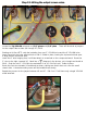
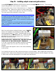
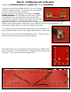
Refer to the photo at the bottom of this page or the BUSS
WIRING DIAGRAM in the APPENDIX for buss wire locations.
Using 22g buss wire and small pliers, wrap a full rotation
around the first terminal, squeeze in place and route the buss
on to the next terminal. Cut sleeving to length (where
applicable) and slide it in place over the buss wire. Repeat the wrap process at the next terminal.
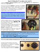
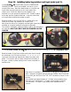
Solder in place making sure the solder flows evenly between the buss wire and terminal. Our
terminals are double-tinned to ensure they readily accept solder.
Try to keep the buss wire and solder at the bottom of the terminal since
many terminals will also have a wire wrapped around them in a later step.
Work your way across the board installing buss wires. There are twelve
buss wires total, and seven positions require sleeving.
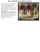
Note that the buss wire connecting four terminals near the LOWER, LEFT
part of the board is one continuous piece, wrapped around each terminal in
succession. This is part of the bias voltage circuit.