
Technical information
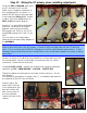
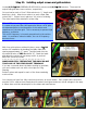

Step 25: Final chassis wiring prior to board install.
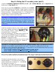
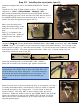
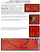
Locate (1) 1,000pf ceramic disk cap (102K). Cut the leads to ½” in
length and solder in place on terminals 1 and 2 of the PRE-AMP pot.
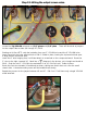
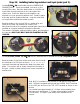
Locate (6) BOARD MOUNTING SCREWS and install in the chassis
using the hardware sequence:
SCREW – CHASSIS – LOCK WASHER – SPACER – NUT – NUT
Install the screw, washer, spacer and one nut. Tighten with a ¼”
nut driver, then install the second nut and tighten against the first.
NOTE: on the initial run of chassis for this kit we had the screw
hole too near the choke, just as Marshall did on the original 2203
amps. You may need to loosen the choke mounting screws to
insert the board mounting screw.
This was adjusted on the second run of chassis.
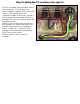
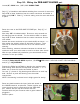
Your chassis is almost ready for the board to be wired in place. Just twist the OT primary center tap
wire (WHITE) and the RED choke wire together for approximately 4”.
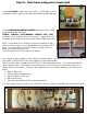
This concludes what I consider to be SECTION 2 of the assembly process. Your chassis should look
like the picture below. Everything is mounted except for the AC power socket and the mains fuse
holder, which are wired last. Five wires are hanging loose in the chassis, waiting to be wired to the
board:
• Blue PT bias wire
• Violet negative feedback wire
• Yellow output screens wire
• Black choke wire
• Red choke wire/White OT wire (twisted together)
If you are happy with your work so far, proceed to the next steps of assembling the component board!