
Technical information
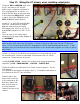
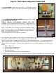

Step 22: Installing balancing resistors and input jacks (part 1).
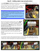
Locate (2) 56kΩ 2W metal oxide resistors (GREEN-BLUE-
ORANGE-GOLD). These are installed, one each, on the
screens filter caps. Bend the leads under on one 56k and
route them through terminals on the cap nearest the
chassis rear. Route the lead from the negative cap
terminal on to the ground lug bottom hole. Solder in place
at the lug and the negative terminal. Loop the other lead
on the positive terminal and solder in place.
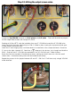
Bend the leads for the second 56k in a similar way and
install on the filter cap nearest the chassis front.
Note that the lead on the negative terminal gets looped and soldered in place, while the other lead is
installed as a jumper between the positive terminals.
The resistors should be soldered solidly in place, perched above
the caps and MUST NOT BE AT RISK OF SHORTING ON THE
CHASSIS.
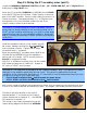
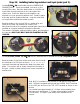
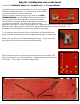
Locate (2) CLIFF JACKS, (1) 1MΩ 1W resistor (BROWN-BLACK-GREEN-GOLD), (6”) 22g BLACK wire.
Bend the leads of the 1MΩ resistor and route them through
the terminals of a Cliff jack as shown. >>>>>>>>>
Loop each terminal and squeeze the leads into place with
pliers. The resistor will sit neatly tucked into the body of
the jack. Solder in place leaving room in each terminal for
another wire.
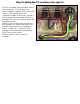
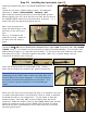
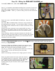
Strip 1 ½” of insulation from the end of a 6” piece of 22g black
wire. Route the stripped end through the LOWER, RIGHT terminal
on the Cliff jack and on to the TOP, LEFT terminal as shown in the
picture.
You should have approximately 4” of black wire extending from
the lower jack, and approx 1” of bare wire extending from the
TOP terminal. The jack is now ready to be installed on the
chassis.