
Technical information
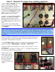
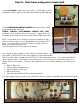

Step 21: Installing output screen and grid resistors.
Locate (4) 5.6kΩ 1W (GREEN-BLUE-RED-GOLD) resistors and (4) 1kΩ 5W resistors. These are the
output tube grid and screen resistors, respectively.
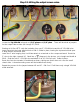
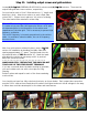
Cut one lead on each of four 5.6kΩ resistors to ¼” length and
bend into a hook. Attach one resistor on each output tube
socket PIN 5. Shown here in place on V4, prior to soldering.
The other lead will be attached in a later step.
TECH NOTE: Attaching a resistor to the output tube grid (pin
5) creates a low pass filter (all frequencies below cut-off pass
un-attenuated) due to the interaction of the resistor and
capacitance of the tube grid. This is necessary to prevent high
frequency oscillation.
The cut-off frequency is inversely proportional to the resistor
value. As resistance value increases, the cut-off frequency
becomes lower.
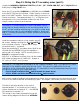
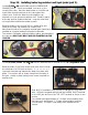
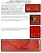
With four grid resistors soldered in place, prep a 1kΩ 5W
resistor for installation by bending the leads under and
spacing approximately ½” apart. Feed the leads into the
top terminal holes of PINS 4 and 6 of V7. Bend the leads
and adjust the resistor as necessary until it is perched
above the socket as shown.
>>>>>>>>>>>>>>>>>>>>>>>>>
MAKE ABSOLUTELY CERTAIN THAT THE LEADS DO NOT
TOUCH ANY OF THE OTHER SOCKET TERMINALS!
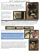
If you are concerned about the leads shorting to terminals,
you can insulate each one with a short piece of 18g
sleeving.
Solder in place and repeat for each of the three remaining
octal sockets.
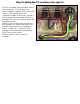
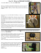
You should now have four fully wired octal sockets, as shown below. Each output tube connection
must be 100% solid as these terminals will conduct the highest and most critical voltages in the amp.
A failure here could be catastrophic for the tubes and transformers.