
Technical information
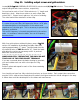
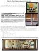

Step 20: Wiring the OT secondary wires (part 2).
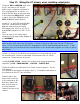
Your OT secondary wires should be routed
as in the picture. The free end of the
VIOLET negative feedback wire is left in the
chassis, it will be attached to the
component board in a later step. All that’s
left to complete the secondary wiring is to
add 18g buss wire to the speaker jacks and
impedance switch.
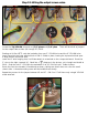
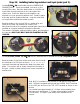
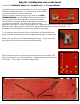
Feed a 6” piece of buss wire through four
jack terminals, as shown, and route to the
terminal in the center of the impedance
switch. Install a 1 ¼” section of 18g
sleeving over the buss wire between the
RIGHT jack and the switch.
Solder in place on each of the five
terminals.