
Technical information
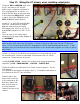
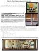

Step 19: Wiring the OT secondary wires (part 1).
Locate the MARSHALL IMPEDANCE SWITCH, (2) #4 – 3/8” SCREW AND NUT, 10” of 18g BUSS and
a 10” piece of 22g VIOLET wire.
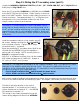
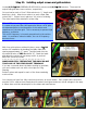
Route the OT secondary COMMON wire (BROWN for the C1998)
to the RIGHT Cliff jack as indicated. Solder in place in the lower
part of the RIGHT terminal. Ensure a solid solder joint as this is a
critical connection. Feed approximately 2 ½” of 18g buss wire
through each of the four terminals nearest the rear of the
chassis, solder in place at each terminal.
TECH NOTE: If you are using an OT with “self-leads”, which
means that the actual windings of the secondary extend out of
the OT and are insulated with sleeving, you need to scrape away
enamel from the ends of each lead before soldering. Noted self-
lead OT’s include the Metroamp C1998V and Mercury Magnetics
O100JM-SL.
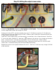
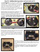
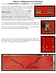
Install the impedance switch on the chassis using (2)
#4 screws, making sure that the “4Ω, 8Ω and 16Ω”
text is oriented correctly. Tighten with a Philips
screwdriver and ¼” nut-driver.
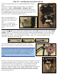
Route the remaining OT secondary wires (BLACK 4Ω,
YELLOW 8Ω and GREEN 16Ω) to the impedance
switch and cut to length. NOTE: see the picture in
Step 20 for suggested routing.
Strip 3/8” of insulation from each wire, tin the strands
with solder and bend into a small hook. Prepare a
10” piece of VIOLET wire the same.
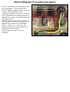
TECH NOTE: The violet wire is referred to as the “negative feedback” wire. It’s purpose is to feed a
small part of the amplifier output back into the circuit. This serves to stabilize the circuit and
contributes to the characteristic Marshall tone. It’s important to note the appropriate terminal to wire
your NF to according to your output tube type:
• EL34’S should be wired to the 8Ω switch terminal (as shown above)
• 6550’s, KT88’s and 6L6’s should wired to the 4Ω switch terminal
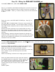
With correct negative feedback wiring determined, attach each secondary wire by squeezing the hook
of wire on the switch terminal and soldering in place. Once again, solid solder joints are critical here.
The BLACK 4Ω wire attaches to the switch
terminal labeled “1” on the back of the switch.
Yellow 8Ω attaches to terminal “2”. And GREEN
16Ω attaches to terminal “3”.
This wiring is also clearly represented in the full
chassis wiring diagram located in the APPENDIX.