
Technical information
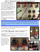
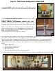

Step 18: Wiring the output screen wires.
Locate the 22g YELLOW wire and cut (3) 5” pieces and (1) 6” piece. These will be wired as jumpers
for the output tube sockets (V4 through V7) PIN 6.
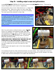
Starting at V4 (far LEFT): strip the insulation from one 5” YELLOW wire and the 6” YELLOW wire.
Insert these into the lower terminal hole of PIN 6. Solder in place, leaving the top terminal hole open.
A large resistor will mount here.
Leave the 6” wire hanging free, it will later attach to a terminal on the component board. Route the
5” wire to the right, towards V5. Bend into a “[“ shape as in the picture, cut to length and install at
PIN 6. Strip the next 5” YELLOW wire and attach it at V5, PIN 6 as well. Solder in place.
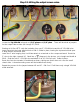
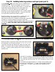
Route the next wire towards V6 and bend as shown, taking care that it does not cover the small
chassis hole. A board mounting screw will be installed here shortly.
Repeat the process for the jumper between V6 and V7. PIN 6 on V7 will have only a single YELLOW
wired attached.