
Technical information
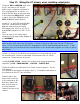
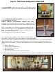

Step 17: Wiring the OT primary wires, installing output jacks.
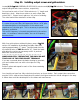
Twist the RED and BROWN wires from
the OT and route to V5 and V6.
Make sure to complete a minimum of
five complete twists, as shown. >>
Attach the RED wire to the lower hole
in the terminal at PIN 3 of V5. Solder
in place. Route the BROWN wire to
PIN 3 of V6 and attach likewise.
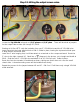
Locate (4”) of each RED and BROWN
22g wire. Install these as jumpers
between octal sockets as shown.
RED jumpers V4, PIN 3 to V5, PIN 3.
And BROWN jumpers V6, PIN 3 to V7,
PIN 3.
You can zoom in for clarity and/or
reference the full amp wiring diagram in
the APPENDIX.
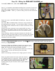
TECH NOTE: Output tube socket pin 3’s are connected together in pairs to allow one pair of output
tubes to drive each side of the OT primary. V4 and V5 drive one side while V6 and V7 drive the
other. This is crucial to the PUSH-PULL arrangement of a100 watt Marshall output section. It also
illustrates why you pull either the two outside tubes or two inside tubes together, as a pair, to reduce
amp output.
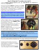
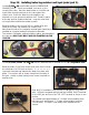
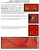
Locate a 4” piece of 22g BLACK wire and attach to the ground lug on the
V5 mounting bolt. Ensure a solid solder connection as this is a critical
connection. Route the wire as shown.
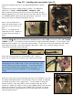
Locate (2) CLIFF JACKS. Install in the chassis holes using the hardware
sequence: JACK – FIBER WASHER – CHASSIS – PLASTIC NUT
Tighten the plastic nut with pliers or a 15mm socket or wrench. Do not
over-tighten.
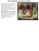
Cut the BLACK ground wire to length, strip ½” of insulation and attach to
the terminal on the LEFT jack as shown.
Solder in place, but
leave room in the top
of the terminal for the
buss wire which will
later connect each of
the four terminals
nearest the rear of the
chassis.