
Technical information


Step 16: Chassis wiring (part 2)
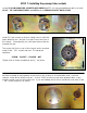
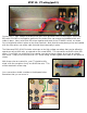
Locate (1) 4.7kΩ 1-WATT CARBON FILM RESISTOR and (1) SOZO .1uf CAPACITOR.
Solder the 4.7k in place between the buss wire and terminal
one of the pot. Later, a VIOLET wire will also attach here.
Next, bend the leads of the Sozo .1uf cap as shown and solder
in place. One lead will attach directly to the pot. The other
will attach to (and act as a jumper between) terminals 2 and 3.
TECH NOTE: It is common to find a .68uf cap in place of the .1uf on
many JMP Marshall amps. In my research, .1uf appeared to be more
common, which is why I selected it as stock for the kit. It is worth trying
the .68uf value here though, as it changes the frequencies affected by the
PRESENCE control.
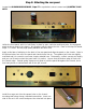
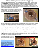
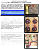
Locate RED 22g 600V wire. Cut (2) 4” pieces of RED wire and
strip 1 ½” of insulation from one end of each. Feed the
stripped end of one wire through the LEFT, positive terminal of
the grounded mains cap (TOP, RIGHT in the picture). >>>>
Wrap the bare wire one complete turn around the terminal and
route to the second positive terminal. Again, wrap the bare
wire one complete turn.
Solder in place. Route the loose end to the negative terminal of
the adjacent mains cap (LOWER, RIGHT) and cut to length.
Strip ½” of insulation and wrap, then solder in place.
Repeat for the screens caps (LEFT).
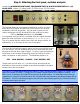
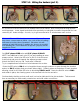
Locate (1) JMP STYLE FUSE HOLDER and mount it on the
chassis in the “HT, 1 amp” labeled position. Note that the
flatted sides of the fuse holder should be aligned with the
flatted edge of the chassis hole.
Tighten the plastic nut with a 14mm wrench or pliers, being
careful not to over-tighten.
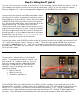
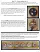
Cut a 14” piece of RED wire and strip 1 ½” of insulation from
one end. Insert the bare wire into the LEFT positive terminal on
the ungrounded mains cap (LOWER, RIGHT), wrap completely
around the terminal and route to the other positive terminal.
Solder in place. Route the wire as shown, to the RIGHT
terminal on the fuse holder and solder in place.