
Technical information


Step 15: Chassis wiring (part 1)
The next several steps are dedicated to wiring inside the chassis in preparation for installing the
component board. This may make it seem as though the instructions are jumping around a bit. Rest
assured, the miscellaneous tasks are all aimed at the same destination.
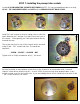
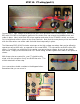
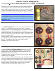
Locate the supplied 18 GAUGE BUSS WIRE (the larger of the two
buss wires in your kit). It will be installed in three positions, two
filter caps and on the back of the pots. Solder buss wire in place
between the negative terminal and the ground lug on both the
preamp filter cap and the mains filter cap nearest the rear of the
chassis. Assure solid solder joints.
NOTE: Ground both the preamp and mains filter caps!
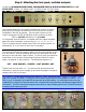
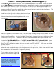
Locate (1) 100kΩ 1 watt carbon film resistor (BROWN-BLACK-
YELLOW-GOLD). Install on the V2 preamp socket (second from the
left), as shown. >>>>>>>>>>>>>>>>>>>>>>>
Cut on lead to about 1/8” long and feed the un-cut end through the
pin 1 terminal. Now slide the cut end into terminal #6. Solder in
place, leaving room in the terminal for the wire that will later attach
here. Bend the long lead around terminal #1 and route over to
terminal #7. Cut to length and solder in place at both #1 and #7.
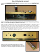
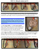
Install a strip of 18 gauge buss wire across the back of all six pots. Solder in place on each pot taking
care not to apply too much heat, as you can damage the pot. A good rule of thumb is to hold your
iron in place on the pot for not more than 5 seconds.
The pots are made specifically to accept solder and you should not have any difficulty making solder
connections that flow seamlessly form the buss wire to the pot.
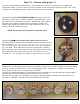
With the buss in place, use 18 gauge buss wire to connect jumpers between the buss and pin 3 of
three pots: MIDDLE, MASTER VOLUME and PREAMP VOLUME.