
Technical information

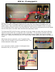

STEP 14: Wiring the heaters (part 2).
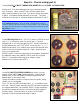
Continue daisy-chaining sockets together until all of the output sockets are wired, as shown above.
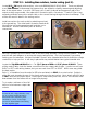
As you move to the left and wire the preamp tube socket heaters, wire routing and twisting become
more important. Lower signal levels and closer proximity to tube grids increases the potential for hum
caused by AC heater voltage. As such, try to get an extra twist of wire between each socket.
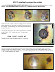
TECH NOTE: 12AX7 tubes have two internal heater filaments
that share a connection at PIN 9. One side of the AC voltage
will connect to this shared terminal. The other AC will
connect to both PIN 4 and 5, making the heaters in parallel
and allowing the 12.6V filaments to operate properly on the
supplied 6.3V AC.
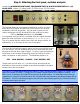
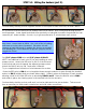
Cut (3) 6” pieces of RED wire and (3) 9” pieces of BLACK.
NOTE: one additional of each color if you are installing an extra
preamp socket. Attach the RED wire to PIN 2 of the left-most
octal socket and route it towards the adjacent preamp socket.
Attach the BLACK wire to PIN 7 and route it likewise.
Try to complete three full twists of wire between the sockets.
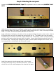
Route the RED wire to PIN 4, cut to length but leave enough conductor to pass through the terminal
and on to PIN 5, bridging them as shown (above right). Solder in place at the bottom of each terminal
allowing a hole for the next RED wire to also bridge PINS 4 and 5. Route the BLACK wire to PIN 9
and solder in place, also leaving space in the terminal hole for the next wire.
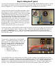
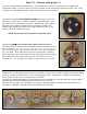
Continue daisy-chaining sockets until each is wired as indicated in the picture below. Take as much
time as necessary to make neatly routed wires and solid solder connections.