
Technical information

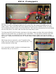

Step 11: Wiring the PT (part 1)
You can now start what I consider to be Section 2 of the assembly. Wiring inside the chassis. Fire up
your soldering iron and we’ll start with the power transformer. NOTE: if you are using the optional
Mercury Magnetics PT, refer to the appropriate diagram in the APPENDIX for wire colors.
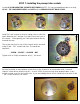
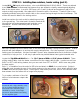
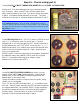
Connect the bias common wire (Blue) and heater center
tap (Green with Yellow) to ground by routing as shown
and soldering to the ground lug. Attach the heavy gauge
GREEN/YELLOW wire to the lower hole on the ground
lug. Be sure that solder flows evenly between all of the
strands and the lug. Clip away any excess wire.
Hold the BLUE bias wire in place at the lug and cut it to
length leaving an extra inch of wire. Strip the insulation
with wire strippers and route the bare wire through the
ground lug and on to the negative terminal of the phase
inverter filter cap, as shown. >>>>>>>>>>>>
Solder in place at the lug and at the terminal.
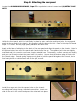
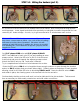
Connect the heater wires (GREEN) to tube socket #7 (seventh socket from the left) also referred to as
“V7” using the synonym “valve” in place of “tube”. Twist the heavy gauge GREEN wires and route,
as shown, to pins 2 and 7 of V7. Strip 1/8” of insulation and solder each in place in the lower
terminal holes. Clip away any excess wire. NOTE: the terminals on the socket will break if bent too
far or too many times.
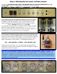
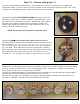
Connect the PT primary wires to the POWER
switch. The lighted rocker switch requires “hot”
and “neutral” AC voltage to light up. As such,
both the common and the voltage tap will be
switched. COMMON for the 1203-80-MS is
ORANGE. Select the primary wire for the
appropriate voltage:
• RED for 120V AC
• BLUE for 220V AC
• VIOLET for 230/240V AC
Twist ORANGE with your selected wire color (RED for 120V operation is pictured) and route to the
POWER switch, as shown. Solder in place with ORANGE on the LEFT silver terminal (indicated on the
switch as “11”) and RED on the RIGHT silver terminal (indicated as “24”). The two unused wires
should be cut to approximately the same length and should have 1/8” SHRINK TUBING applied over
the ends. These will later be bundled with the other wires and secured in place with cable ties.