
Install Instructions


2
RECEIVING AND INSPECTION
Upon receiving the product, check to make sure all
items are accounted for by referencing the Bill of Lading
to ensure all items were received. Inspect each carton
for shipping damage before accepting delivery. Notify
the freight carrier if any damage is noticed. The carrier
will make notification on the delivery receipt
acknowledging any damage to the product. All damage
should be noted on all copies of the Bill of Lading which
is countersigned by the delivering carrier. A Carrier
Inspection Report should be filled out by the carrier
upon arrival and a report given to the Traffic
Department. If damaged upon arrival, file a claim
immediately with the carrier. Any physical damage to
the unit after acceptance is not the responsibility of
Mars Air Systems.
UNPACKING
Verify that all parts, components and accessories, and
the correct quantities of each have been received. If
any items are missing, report shortages to Mars Air
Systems directly to arrange for obtaining the missing
items. Again, verify quantities received against those
on the Bill of Lading only, as multiple shipments may be
involved.
INSTALLATION
Typical Mounting – Wall or Ceiling Mounted
Horizontally Above the Door Opening
1. Remove the air intake grille(s) and/or filter(s) from the
product and set aside. Only products 48” or less,
except HV2 and EP2 models, are shipped with the
motor fan assembly (MFA) mounted inside.
2. Measure the housing and center it over the opening.
The air curtain shall be equal to or greater than the
width of the opening.
3. Total of two (2) key-hole slots and six (6) pre-punched
mounting holes are provided for your convenience.
The 7/16” pre-punched holes (4) provided, (2) on each
end for top/celling mounts. The 1/2” key-hole slot and
7/16” pre-punched hole (2) provided, (2) on each end
for wall mounts. These holes must be utilized to secure
the product to the wall or ceiling. If necessary, holes
may be drilled inside the product
to align with the stud
spacing. All hardware is field provided by others.
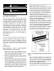
4. Mount the product such that the discharge is 1” above
the opening and all obstacles. (FIG. 1)
Note: If the product is installed higher than the
recommended 1” above the opening, then it must be
moved 3/8” away from the wall for every 1” that it is
moved up. Any void between the wall and the product
must be sealed, by others, to optimize performance.
5. Use four (4) threaded rods for overhead installation or
four (4) threaded bolts for wall installation. All
hardware is field provided by others. (FIG. 1)
6. If applicable, optional Adjustable Mounting Brackets,
Side Extension Plates and Extended Wall Mounted
Brackets are also available for installations over a
Vertical Lift or Drum Roll-up type door. (Reference
Accessory Installation Supplement)
7. If applicable, for tandem installation or products
mounted side by side, allow no more than 6” between
the two products. For overhead installation using
threaded rods, the products may require a beam, by
others, to span the full distance of the mounting length.
(Reference Accessory Installation Supplement)
8. All wires must be connected internal of the unit and
some knockouts are provided. However, it may be
necessary to create your own knockout, as required.
9. The unit must be wired per NEC and local codes.
FIG. 1
Motor Fan Assembly Installation and Electrical Field
Wiring
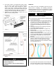
1. Once the housing is installed over the opening, the
Motor Fan Assembly (MFA) must be re-placed and
securely fastened. For products with the MFA shipped
loose, wing nuts or hex nuts are provided inside the
unit (FIG. 2). For heated MFA installation, reference
Heated Products Supplement Sheet.
2. The unit and any optional accessories must be wired
with the proper voltage to the junction box per the
wiring diagram. (FIG. 3, unheated products only)
WARNING
Precaution should be taken in explosive atmospheres.
WARNING
When servicing the product, motor may be hot enough
to cause pain or injury. Allow motor to cool before
servicing.