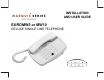
® INSTALLATION AND USER GUIDE EUROMW5 or MW10 DELUXE SINGLE LINE TELEPHONE Copyright TeleMatrix Inc.
SAFETY AND COMPLIANCE DOC - NOTICE AND LOAD NUMBER STATEMENT NOTICE: The Canadian Department of Communications label identifies certified equipment. This certification means that the equipment meets certain telecommunications network protective, operational and safety requirements. The Department does not guarantee the equipment will operate to the user's satisfaction.
SAFETY AND COMPLIANCE FCC Part 15 Compliance Warning Changes or modifications to this unit not expressly approved by the party responsible for compliance could void the user's authority to operate the equipment. NOTE: This equipment has been tested and found to comply with the limits for Class B digital device, pursuant to Part 15 of the FCC Rules. These limits are designed to provide reasonable protection against harmful interference in a residential installation.
IMPORTANT SAFETY INSTRUCTIONS When using your telephone equipment, basic safety precautions should always be followed to reduce the risk of fire, electric shock and injury to persons, including the following: 1. Read and understand all instructions. 2. Follow all warnings and instructions marked on the product. 3. Unplug this product from the wall outlet before cleaning. Do not use liquid cleaners or aerosol cleaners. Use a damp cloth for cleaning. 4.
IMPORTANT SAFETY INSTRUCTIONS 1. 2. 3. 4. Never install the telephone wiring during a lightning storm. Never install the telephone jacks in wet locations unless the jack is specifically designed for wet locations. Never touch un-insulated telephone wires or terminals unless the telephone line has been disconnected at the network interface. Use caution when installing or modifying telephone lines.
CONTENTS Features ...........................................………..……………………………………................................... 7 Controls ...........................................................................……………………………………………….. 8 Definitions of Controls ………………………………………………………………………………………. 9 Installation .....................................................................……………………………………………........ 10 Wall Mounting .....................................….......................……………………………………………........
FEATURES • • • • • • • • • • • • • • • • • One Line Convenient Data Port No Battery Maintenance TouchLiteTM One Touch Message Retrieval Feature Switch Selectable Message Waiting Tone Dialing 5 or 10 Secure Programming Speed Dial Memory Locations Programmable Flash Function (100mS, 600mS) Pause Function (3.
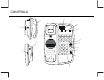
CONTROLS 15 2 12 14 HANDSET 4 13 NEON LR1 LR2 STORE LED SIE TYPE 1 10 11 9 FOR MESSAGES 1 2 3 PRESS HERE 5 6 DATA 4 REDIAL 7 R ECALL 3 8 8 9 HI 7 LIN E 1 VOL LOW * 0 # 5 6 FIGURE 1 8
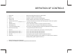
DEFINITION OF CONTROLS 1. Handset Clip ………………………………….. Retains the handset when the phone is wall mounted. 2. Handset ..........…………..………….........…... Hearing aid compatible, low profile styling. 3. Ringer Control ………….……….……………. Adjusts the volume of the ringer to HI/LOW setting. 4. Handset Jack ……………………………….… Modular receptacle where handset cord plugs into the base unit. 5. Handset Volume Control Increases or decreases the loudness of the receiving speech volume when pressed. 6.
INSTALLATION CONTENTS: Packaged with Each EUROMW5 or MW10 Telephone: (Figure 2): FOR MESSAGES ● Base Unit ● Handset ● 15’ Line Cord ● Coiled Handset Cord ● Clear Plastic Overlay ● Paper Index Card ● Instructions ● Optional Wall Mounted Plate 1 2 3 4 5 6 7 8 9 PRESSHERE REDI AL RECALL VOL * 0 # FIGURE 2 TO PREPARE THE EUROMW10 TELEPHONE FOR USE: 1. Plug one end to the modular handset cord into the modular receptacle on the left side of the unit.
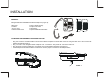
WALL MOUNTING 1. 1. 2. 3. HANDSET RETAINING HOOK UNSNAP ROTATE 180 . SNAP INTO PLACE. A removable clip to hold the handset secure when in the wall mounted position is located below the hook switch. FIGURE 5 Remove the clip hook, turn it 180 degrees round and slot it back into place (figure 5). 2. INSTALLATION FOR WALL MOUNTING M OUNTING WEDGE Plug one end of the line cord into the line jack on the top of the base unit. LABEL-IC LABEL-S/NO. LABEL-FCC 1.PRES S THE RELEAS E TABS . 2.SNAP INTO PLACE.
MESSAGE WAITING FEATURE The EURO telephone is equipped to support a number of standard Message Waiting Systems: Neon, line reversal, LED and Siemens (optional Siemens MW board is available from Telematrix Equipment LLC). The Message Waiting System (MW) is pre-set at the factory as indicated by the original order. The programming is done prior to delivery and should only be changed by authorized personnel.
MESSAGE WAITING PROGRAMMING The message waiting selector switches is located underneath the faceplate. To access remove the clear plastic overlay using a pointed object such as a paperclip and lift off the clear plastic overlay. Re-insert the overlay by aligning one side of the tabs on the overlay into the slots next bend the overlay in the middle and insert the remaining tabs on the other side. Message Waiting This telephone is standard equipped to support a number of message waiting systems.
TouchLiteTM FEATURE PROGRAMMING Feature Description TouchLitetm is a new innovation that integrates the visual message waiting lamp and a speed dial button, all in one. It allows easy access for guests to retrieve messages. When the message-waiting lamp lights to notify the guest that a message is waiting. A simple press of the red TouchLitetm key connects the guest to the message center or front desk. TouchLitetm also adds an additional memory location to this telephone. Programming TouchLite tm 1. 2. 3.
OPERATION PLACING A CALL USING THE HANDSET Lift the handset; the phone will select the line. Listen for dial tone and adjust the volume control if necessary. Dial out by using the numeric dial pad or by pressing the redial/pause button or by pressing a speed dial button. To end the call, place the handset on hook. RECEIVING A CALL When the phone rings, pick up the handset. Adjust the volume control if necessary.
OPERATION Programming a Flash Timing Delay into Speed Dial Memory Flash Timing can be programmed into the Euro Series Telephones speed dial memory. This function allows the user to include a timed line break in the sequence of the dialing patterns when using the speed dial keys. This function may be required for accessing line features provided by your telephone system or local telephone company.
OPERATION FLASH OPTIONS (STANDARD PROGRAMMING) The EURO Series is pre-programmed with two standard flash options: 1. Option 1 is the programmable 100ms flash timing 2. Option 2 is the standard default of 600ms flash timing. To change the flash to option 2, the 600ms flash timing: 1. 2. 3. 4. 5. 6. Lift the handset. Press the 'store' button to enter the programming mode. Press digit 2 using the numeric dial pad. Press digit 1 using the numeric dial pad.
OPERATION Programming A Pause into Memory Pause(s) can be programmed into the number pattern when speed dial programming memory. This function allows the user to delay the dialing pattern of a number. This function may be required for accessing line features provided by your telephone system or local telephone company. For example, a speed dial number may need to pause during its dialing sequence to insure proper connections. Multiple pauses can be programmed into speed dial for added pause time.
OPERATION Handset Volume Control The EURO Series telephone is equipped with an ADA/FCC compliant handset volume control located on the face of the phone. When the “Volume” key is pressed, the volume of the handset receiver is increased by 12-15 decibels. The “Volume” key is a slide switch volume control. When pressed in the upward arrow position, the volume will increase. When pressed in the downward arrow position, the volume will decrease.
OPERATION USING THE DATA PORT The EURO Series is equipped with a convenient port on the right side of the base unit. This modular receptacle is used to plug in any standard telephone device such as a computer modem, answering machine or fax machine.
CARE AND MAINTENANCE Keep the telephone dry. If it gets wet, wipe it dry immediately. Liquids might contain minerals that can corrode the electronic circuits. Use and store the telephone only in normal temperature environments. Temperature extremes can shorten the life of electronic devices, damage batteries, and distort or melt plastic parts. Keep the telephone away from excessive dust and dirt that can cause premature wear of parts.
SERVICE INFORMATION When problems arise during installation or service that cannot be resolved using this or related documents, contact the TeleMatrix Technical Service department 8:30a.m. - 4:30p.m. MST: Toll Free: 1-800-462-9446 Direct: 719-638-8821 Fax: 719-638-8815 www.telematrixusa.com Many times a problem is either installation or user related. Please contact TeleMatrix PRIOR to sending a telephone to our service center for repair. In the unlikely event that a factory repair be necessary: 1.
STATEMENT OF LIMITED WARRANTY STATEMENT OF LIMITED WARRANTY TeleMatrix, Inc.