DOOR DOORPHONE150 PHONE 150 ™ USER MANUAL 3 GEBRAUCHSANLEITUNG 25 GUIDE UTILISATEUR 47 MODO DE EMPLEO 69 MANUALE D’ISTRUZIONI 91 GEBRUIKSAANWIJZING 113 20465/20140403 • DOORPHONE 150™ ALL RIGHTS RESERVED MARMITEK ©
© MARMITEK
TABLE OF CONTENTS ............................................................................ 3 SAFETY WARNINGS ............................................................................... 3 INTRODUCTION ....................................................................................... 4 FEATURES ............................................................................................... 4 STANDARD ACCESSORIES....................................................................
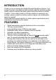
INTRODUCTION Thank you for purchasing this Digital Wireless Doorphone System. Your system has been manufactured and checked under the strictest possible quality control to ensure that each system leaves the factory in perfect condition. In the unlikely event you find any defect or experience any problem, please contact our service centre or dealer, do not attempt to repair by yourself. Please read this manual carefully to obtain optimum performance and extended service life from the system.
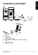
ENGLISH STANDARD ACCESSORIES a. b. c. d. e. f. g. h.
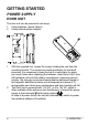
GETTING STARTED POWER SUPPLY DOOR UNIT The door unit can be powered in two ways. 1. Using batteries. (power failure) 2. Using external power adapter. 1. 2. 6 With the supplied tool, loosen the screws holding the unit from the mounting bracket. The screws are made specifically for anti-theft purposes, it is necessary to keep the tool in a safe place for when you need it later when replacing the batteries. Insert three UM-4 size AAA alkaline cells into the battery compartment, observing correct polarity.
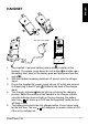
ENGLISH HANDSET TO AC OUTLET 1. 2. 3. 4. 5. The supplied Li polymer battery pack is already installed in the handset. (To replace, press down the lock button and slide open the battery door, take out the battery pack and disconnect from the socket .) With the handset remaining switched off, place it onto the charger stand. Plug in the supplied AC power supply into an AC outlet and connect its output plug to the DC jack located at the back of the charger stand.
6. Now the unit can be switched on and ready for operation. Taking out the unit or keeping it placed in the charger stand will cause no damage to the battery. In the latter case, when the battery is being consumed and the voltage falls to a certain level, the charger stand will automatically charge up the battery. The segments inside the will flash in turn whenever the unit is under charged.
N.B. In case you are having two or more handsets as well as a back gate Door Unit, always perform the pairing process with all Door Units and handsets together and with the handsets being set in pairing mode first. Remember every time you add on new units to the system, either handset or Door Unit (for back gate use), it is necessary to perform the pairing process all over again with all the units together or otherwise the new units will not work with your original system.
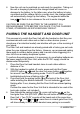
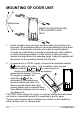
MOUNTING OF DOOR UNIT Drilled holes INSERT PLUGS INTO HOLES (FOR CONCRETE WALL ONLY) 1. Select a location near your door entrance where the surface is not too rough. We recommend that you do some polishing to get a plane surface or otherwise the unit may not be able to mount properly. It should be noted that the mounting bracket should not be installed on metal screening surfaces or in the vicinity of other electronic devices that may reduce the operating range.
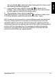
ENGLISH Always close These two terminals normally provide a 12V supply. During communication, once the door lock opening button is pressed, this voltage will drop to 0V temporarily for 15 seconds. Always open These two terminals normally provide 0V. During communication, once the door lock opening button is pressed, the terminals will provide a 12V supply temporarily for 15 seconds. Under no circumstances should AC mains Voltage be directly connected to the terminal blocks ! 3.
CONTROLS LAYOUT Door Unit Handset 1. 2. 3. 4. 5. 6. 7. 8. 9. 10. 11. 12 Call button Microphone Speaker Call indicator Light sensor Temperature sensor Pairing button Terminal block Volume up button Volume down button Answer button Charging Stand 12. Hang up and power ON/OFF button 13. Door lock open button 14. Press-to-talk (PTT) button 15. Microphone 16. Battery door lock button 17. Speaker 18. Li battery socket 19. Charging contacts 20. Charging indicator 21.
ENGLISH LCD 1. 2. 3. 4. 5. 6. 7. 8. 9. 10.
Flashing Steady light up A. Front gate doorbell ringing B. Back gate doorbell ringing C. Missed call, F (Front gate) B (Back gate) D. Reception mode E. Out of range alert F (Front gate) B (Back gate) F. Door chime alert selected G. Flashing light alert selected H. Vibrating alert selected I.
Door chime and vibrating alert selected K. Flashing light and vibrating alert selected L. Door chime, flashing light and vibrating alert selected M. Door lock opened N. Door Unit battery low F (Front gate) B (Back gate) O. Handset battery low P. Handset Battery level Q. Speaker volume R. Door lock de-activated DoorPhone 150 ENGLISH J.
OPERATION 1. Switch on the handset with a long press (over 3 seconds) of the Power ON/OFF button . Press the same button again in case you want to switch off the unit. 2. The LCD screen will show up. In case the handset battery low icon O appears and an alarm is heard, the battery has run down and needs to be recharged by placing the unit onto the charger stand. During charging, the segments inside the battery level icon P will flash in turn irrespective if the unit is switched on or off.
Upon receiving a call, either icon A or icon B will appear on the screen, depending if the call is from the front gate or back gate (in case you have purchased an optional Door Unit for back gate). The handset can answer the call by pressing the Answer button and the reception mode icon D will show up in LCD. Now conversation is possible and the voice of the visitor can be .
10. 11. 12. 13. 14. 15. Door Unit. The remaining handsets will return to standby mode and their buttons will become de-activated until the conversation ends, making it impossible for them to interfere with the conversation. Under the circumstances of an unanswered call from a visitor (e.g. you are away from home or located at a place which is out of range will appear on the screen. This from the Door Unit), the icon C icon is useful to remind you that somebody has called.
This function is applicable only if you have two or more handsets. Please note all units must be paired together. a. Under standby mode, momentarily press the Answer button , a “do – do” sound will be heard. b. The called handset will show the selected incoming call alert. Press the Answer button to answer the call. The “do-do” sound on the calling handset will stop. c. Now both handsets can converse with each other using the PTT button . d. Either party can press the Hang up button to end the conversation.
PRECAUTION x x x x x x 20 Use only the supplied AC switching power supply. Use of another supply may cause damage to the handset. Do not mix old and new alkaline batteries in the Door Unit. When not using the doorphone for a long period of time, remove all batteries from the handset and Door Unit to avoid battery leakage. Do not leave the handset exposed to strong sunlight for a long period of time or near any heat source, moisture and excessively dusty environments.
Problem Handset and Door Unit cannot communicate Possible Causes Handset and Door Unit has different ID code Battery has run down Communication distance becomes shorter Many steel structures between Handset and Door Unit Battery has run down Out-of-range alert always on No power supply to Door Unit Self battery low icon always on Battery pack is damaged and cannot be recharged.
TECHNICAL DATA Handset Power: Charger: Power consumption: Active Doorbell Dimensions: Door unit Range Backup Power Power adapter Frequency Power consumption Active Material Connection Ambient temperature: IP value Dimensions Rechargeable Li battery pack 1100mAh 3.7V 6V 300mA Stand-by 36mA Transmission mode 130mA Reception mode 270mA Selectable audio, visual or vibration alert 50x142x22mm Up to 450m in free field, up to 50m through walls and ceilings.
COPYRIGHTS Marmitek is a trademark of Pattitude B.V. DoorPhone 150™ is a trademark of Marmitek B.V. All rights reserved. Every effort has been made to ensure that the information in this manual is accurate. Marmitek is not responsible for printing or clerical errors. Copyright and all other proprietary rights in the content (including but not limited to model numbers, software, audio, video, text and photographs) rests with Marmitek B.V.
© MARMITEK
INHALTSVERZEICHNIS ......................................................................... 25 SICHERHEITSHINWEISE ...................................................................... 25 EINFÜHRUNG ........................................................................................ 26 FUNKTIONEN ......................................................................................... 26 STANDARDZUBEHÖR ........................................................................... 27 LOS GEHT’S .........
EINFÜHRUNG Herzlichen Glückwunsch zum Erwerb dieser digitalen, drahtlosen Türsprechanlage. Ihr DoorPhone 150 wurde unter den strengsten Qualitätsanforderungen hergestellt und kontrolliert, sodass ein jedes System in makellosem Zustand das Werk verlässt. Für den unwahrscheinlichen Fall, dass Sie dennoch einen Defekt oder ein Problem entdecken bitten wir Sie, sich mit Ihrem Händler in Verbindung zu setzen. Versuchen Sie niemals das Problem selbst zu beheben.
DEUTSCH STANDARDZUBEHÖR a. b. c. d. e. f. g. h.
LOS GEHT’S SPEISUNG AUSSENSTATION Die Außenstation kann auf zweierlei Art gespeist werden: 1. mit Batterien (Notstrom) 2. mit externem Speisungsadapter 1. 2. 28 Lösen Sie mit dem enthaltenen Schraubenzieher die Schrauben, womit die Station auf dem Halter montiert ist. Mit den speziellen AntiDiebstahlschrauben ist eine hohe Produktabsicherung gegeben. Bewahren Sie den Schraubenzieher für den Fall Sie ihn später nochmals zum Wechseln der Batterien benötigen an einem sicheren Ort auf.
DEUTSCH HANDSET ZUR STECKDOSE 1. Der enthaltene Li-Polymer Akku ist im Handset installiert. (Zum Wechseln der Batterien drücken Sie die Verschlusstaste nach unten und schieben das Batteriefach auf. Entfernen Sie nunmehr den Akku und lösen Sie den Anschluss .) 2. Stellen Sie das noch ausgeschaltete Handset in die Ladeschale 3. Stecken Sie den enthaltenen Speisungsadaptor in die Steckdose und verbinden Sie den Stöpsel mit dem Gleichstromanschluss hinten an de Ladeschale. 4.
wird die Ladeschale den Akku automatisch laden wenn der Akku genutzt wird oder der Spannungsmesser ein bestimmtes, zu geringes Niveau misst. Die Segmente m Symbol werden abwechselnd blinken wenn das Handset unzureichend geladen ist. ACHTUNG: PRÜFEN SIE NACH, OB DER AKKU IM HANDSET WIRKLICH EIN AUFLADBARER IST, BEVOR SIE DAS HANDSET IN DIE LADESCHALE STELLEN, DA ES SONST ZU EINER EXPLOSION FÜHREN KÖNNTE.
N.B. Wenn Sie zwei oder mehr Handsets und auch eine HintertürAußenstation haben, dann müssen Sie das Paarungsverfahren immer mit allen Außenstation und Handsets durchführen und mit den Handsets zunächst im Paarungsmodus. Beachten Sie, dass Sie, wenn Sie neue Einheiten, egal ob ein Handset oder eine Außenstation (für die Hintertür), an das System hinzufügen möchten, das Paarungsverfahren immer für sämtliche Einheiten gleichzeitig gänzlich erneut stattfinden muss. .
MONTAGE DER AUSSENSTATION DÜBEL FÜR LÖCHER VERWENDEN (NUR IN BETONWÄNDEN) Bohrlöcher 1. Wählen Sie einen Ort nahe der Tür mit nicht zu rauer Oberfläche. Zur korrekten Befestigung der Außenstation auf einem glatten Untergrund empfehlen wir, die Oberfläche zunächst gut zu säubern. Berücksichtigen Sie, dass der Halter nicht auf Metallrosten oder nahe anderer elektronischer Geräte angebracht werden darf, um die Funkreichweite nicht zu verringern.
Die zwei gängigsten Türschlossarten die zurzeit auf dem Markt sind, sind entweder “immer geschlossen“ oder “immer offen“. Immer offen Diese zwei Anschlusspunkte werden normalerweise mit 0 V gespeist. Während der Kommunikation werden diese Anschlusspunkte, sowie die Tür-Schließen-Taste betätigt wird, kurz (15 Sekunden lang) mit 12 Volt gespeist werden. Der Netzstrom (230V) darf niemals unmittelbar an die Anschlusklemmen angeschlossen werden! 3.
BEDIENUNGSÜBERSICHT Außenstation Handset 1. 2. 3. 4. 5. 6. 7. 8. 9. 10. 11. 34 Klingeltaste Mikrofon Lautsprecher Klingelanzeiger Lichtsensor Temperatursensor Paarungstaste Anschlussklemmen Ton-Lauter-Taste Ton-Leiser-Taste Beantworten-Taste Ladeschale 12. Auflegen und EIN/AUSTaste 13. Türschloss Öffnen Taste 14. Press-to-Talk (PTT) Taste 15. Mikrofon 16. Batteriefachverschluss 17. Lautsprecher 18. Li-Akku Anschluss 19. Ladeanschluss 20. Ladeanzeige 21.
DEUTSCH LCD 1. 2. 3. 4. 5. 6. 7. 8. 9. 10.
Blinkend Kontinuierlich leuchtend A. Haustürklingel läutet B. Hintertürklingel läutet C. Verpasster Aufruf, F (Haustür), B (Hintertür) D. Empfangsmodus E. Warnzeichen für Außer Funkreichweite F (Haustür) B (Hintertür) F. Türklingelwarnung definiert G. Blinklichtwarnung definiert H. Vibration definiert I.
Türklingel und Vibration definiert K. Blinksignal und Vibration definiert L. Türklingel, Blinksignal und/oder Vibration definiert M. Türschloss geöffnet N. Batteriepegel Außenstation schwach F (Haustür) B (Hintertür) O. Handset Batteriepegel schwach P. Handset Batteriepegel Q. Lautsprechervolumen R. Türschloss abgeschaltet Doorphone 150 DEUTSCH J.
DER BETRIEB 1. 2. 3. 4. 5. 38 Schalten Sie das Handset ein, indem Sie die EIN/AUS-Taste mindestens 3 Sekunden lang festhalten. Um das Handset auszuschalten drücken Sie nochmals diese Taste. Das LCD Display erscheint. Wenn das Handset Batterie-SchwachSymbol O erscheint und ein Alarm ertönt, ist der Akku fast leer. Laden Sie den Akku auf, indem Sie das Handset in die Ladeschale stellen. Während des Aufladens blinken die Segmente im Batteriepegelsymbol P , egal ob das Handset ein- oder ausgeschaltet ist.
7. 8. Doorphone 150 39 DEUTSCH 6. Ton und blinkt der Klingelanzeiger zweimal, um anzuzeigen, dass die Einheit im Stand-by Modus ist. Wird das Gespräch beantwortet, dann leuchtet der Klingelanzeiger kontinuierlich und ertönt der Ding-Dong nicht mehr. Eskann jetzt in das Mikrofon gesprochen werden. .
Drücken Sie im normalen Modus kurz die Taste . Drücken Sie . Das daraufhin binnen 2 Sekunden kurz auf die Taste Türschloss Abgeschaltet Symbol R erscheint im LCD Display. Einschalten Türschloss Öffnen Funktion Gehen Sie gleichermaßen vor wie oben beschrieben. Das Türschloss Abgeschaltet Symbol R erlischt im LCD Display. 9. Für Systeme mit mehreren Handsets gilt, dass alle Handsets bei einem eingehenden Gespräch alarmiert werden.
WECHSELSPRECHANLAGE Diese Funktion findet Anwendung, wenn Sie zwei oder mehr Handsets haben. Achtung: Alle Einheiten müssen kollektiv gepaart werden. a. Drücken Sie im Stand-by Modus die Antworttaste . Ein “Aufruf” Ton erklingt. b. Das angerufene Handset zeigt die definierte Meldung für ein eingehendes Gespräch. Drücken Sie die Antworttaste um den Aufruf zu beantworten. Der “Do-Do” Ton auf dem anrufenden Handset hört auf. c. Nun können beide Handsets über die PTT Taste miteinander sprechen.
ACHTUNG: Die beiden Handset sind möglicherweise nicht in der Lage, einen Aufruf von der Außenstation zu detektieren. Wir empfehlen deshalb, ein Wechselgespräch möglichst kurz zu halten. VORSORGEMASSNAHMEN x x x x x x 42 Verwenden Sie nur die enthaltenen Schaltnetzteile. Die Verwendung anderer Schaltnetzteile kann das Handset beschädigen. Kombinieren sie keine alten und neuen Alkali-Mangan Batterien in der Außenstation.
Problem Handset und Außenstation können nicht kommunizieren. Mögliche Ursachen Handset und Außenstation haben verschiedene ID-Codes. Batterie ist leer. Gesprächsreichweite wird kleiner. Viele Stahlbauten zwischen Handset und Außenstation. Batterie ist leer. Außer Reichweite Meldung wird fortwährend wiedergegeben. Keine Stromversorgung zur Außenstation. Selbsttest BatterieSchwach-Symbol bleibt an. Türschloss kann nicht mit dem Handset bedient werden. Akku ist beschädigt und kann nicht geladen werden.
TECHNISCHE DATEN Handset Speisung: Ladeschale: Stromverbrauch: Aktiv: Türklingel: Maße: Außenstation Reichweite: Speisung Notstrom: Speisung Stromnetz (Klingeltrafo): RF Frequenz: Stromverbrauch: Aktiv: Material: Anschlüsse: Umgebungstemperatur: IP Wert Maße: Aufladbarer Li-Akku 1100mAh 3.7V 6V 300mA Stand-by 36mA Sendemodus 130mA Empfangsmodus 270mA. Wählbar Audio-, Bild- oder Vibrationssignal.
COPYRIGHT Marmitek BV ist ein Warenzeichen von Pattitude DoorPhone 150™ ist ein Warenzeichen von Marmitek BV Alle Rechte vorbehalten. Weitergehende Ansprüche sind ausgeschlossen, insbesondere übernimmt Marmitek BV keine Gewähr für die Richtigkeit des Inhalts dieses Handbuchs. Urheber- und andere Eigentumsrechte am Inhalt (einschließlich aber nicht beschränkt auf, Modellnummern, Software, Audio, Video, Text und Fotos begrenzt) liegt bei Marmitek BV.
© MARMITEK
TABLE DES MATIÈRES ......................................................................................... 47 CONSIGNES DE SÉCURITÉ ................................................................................. 47 INTRODUCTION .................................................................................................... 48 FONCTIONS ........................................................................................................... 48 ACCESSOIRES STANDARD ..................................
INTRODUCTION Félicitations pour l'achat de ce Système d'Interphone Numérique sans Fil. Votre DoorPhone 150 a été fabriqué et testé conformément aux contrôles de qualité les plus stricts, afin que chaque système quitte l'usine en parfait état. Dans le cas improbable où vous décèleriez un défaut ou une anomalie, veuillez contacter votre distributeur. Surtout n'essayez jamais de résoudre le problème vous-même.
FRANÇAIS ACCESSOIRES STANDARD a. b. c. d. e. f. g. h.
PRISE EN MAIN ALIMENTATION UNITÉ EXTÉRIEURE L'unité extérieure peut être pourvue d'une alimentation électrique de deux manières : 1. 2. avec des piles. (alimentation de secours) avec un adaptateur secteur externe. 1. Avec le tournevis fourni, dévissez les vis avec lesquelles l'unité est fixée sur le support de montage. Ces vis sont des vis spéciales antivol. C'est pourquoi il est nécessaire de garder le tournevis dans un endroit sûr, au cas où vous en auriez besoin ultérieurement pour changer les piles.
COMBINÉ FRANÇAIS VERS LA PRISE É 1. 2. 3. 4. 5. 6. Le bloc-pile Lithium-polymère fourni est déjà installé dans le combiné. (Pour le remplacer appuyez sur le bouton de fermeture puis faites glisser le couvercle pour ouvrir. Retirez ensuite le bloc-pile et débranchez-le.) Placez le combiné encore désactivé sur le chargeur. Branchez l'adaptateur secteur fourni sur la prise électrique et connectez la fiche sur la prise d'entrée de courant continu située à l'arrière du chargeur.
automatiquement à charger la pile si la pile est utilisée et si la tension descend en dessous d'un certain niveau. Les segments du symbole clignoteront en alternance lorsque le combiné n'est pas suffisamment chargé. ATTENTION : ASSUREZ-VOUS QUE LA PILE DANS LE COMBINÉ EST BIEN UNE PILE RECHARGEABLE AVANT DE PLACER LE COMBINÉ SUR LE CHARGEUR. SINON CELA POURRAIT PROVOQUER UNE EXPLOSION.
N.B. Si vous avez deux combinés ou plus ainsi qu'une unité extérieure sur la porte arrière, vous devez toujours effectuer le processus d'appairage simultanément avec toutes les unités extérieures et les combinés, en mettant d'abord les combinés en mode d'appairage. Veuillez noter que si vous ajoutez de nouvelles unités au système, que ce soit un combiné ou une unité extérieure (pour la porte arrière), qu'il est nécessaire d'effectuer à nouveau le processus d'appairage simultanément pour toutes les unités.
support de montage au mur. 2. S'il y a une alimentation de 8 à 12V, établissez une connexion avec les bornes repérées sur la face arrière de l'unité extérieure. Il y et pour connecter un a également des bornes repérées verrouillage de porte électrique qui peut être alors ouvert à distance avec le combiné. S'il y a une alimentation électrique, le bouton de sonnette s'éclairera automatiquement lorsqu'il commencera à faire sombre.
Toujours fermé Ces deux bornes ont normalement une tension de 12V. Dès que l'on enfonce le Bouton d'Ouverture de Porte cette tension passera temporairement (pendant 15 secondes) à 0V durant la communication. FRANÇAIS Toujours ouvert Ces deux bornes ont normalement une tension de 0V. Dès que l'on ces bornes auront appuie sur le Bouton d'Ouverture de Porte temporairement (pendant 15 secondes) une tension de 12V durant la communication.
APERÇU DU FONCTIONNEMENT Unité extérieure Combiné 1. 2. 3. 4. 5. 6. 7. 8. 9. 10. 11. 12. 56 Bouton de sonnette Microphone Haut-parleur Indicateur de sonnette Capteur de luminosité Sonde de température Bouton d'appairage Bloc de connexion Bouton volume + Bouton volume Bouton Réponse Bouton pour raccrocher et MARCHE/ARRÊT Chargeur 13. Bouton d'Ouverture de Serrure de Porte 14. Bouton Press-to-talk (PTT) 15. Microphone 16. Bouton de fermeture du compartiment à piles 17. Haut-parleur 18.
FRANÇAIS LCD 1. 2. 3. 4. 5. 6. Serrure de porte ouverte La sonnette de la porte d'entrée et de la porte arrière retentissent Température extérieure Mode de réception Volume du haut-parleur Sonnette de porte, lumière clignotante et/ou avertissement par vibration sélectionnés 7. Niveau de la pile 8. Pile de l'unité extérieure faible 9. Serrure de porte désactivée 10.
Clignotant Constamment allumé A. La sonnette de la porte d'entrée retentit B. La sonnette de la porte arrière retentit C. Appel en absence, F (porte d'entrée), B (porte arrière) D. Mode de réception E. Avertissement hors de portée F (porte d'entrée) B (porte arrière) F. G. Avertisseur de sonnette de porte sélectionné H. Voyant d'avertissement clignotant sélectionné I. Avertissement par vibration sélectionné J.
Sonnette de porte et avertissement par vibration sélectionnés L. Voyant d'avertissement clignotant et avertissement par vibration sélectionnés M. Sonnette de porte, voyant d'avertissement clignotant et avertissement par vibration sélectionnés N. Serrure de porte ouverte O. Pile de l'unité extérieure faible F (porte d'entrée) B (porte arrière) P. Q. Pile du combiné faible R. Niveau de pile du combiné S. Volume du haut-parleur T. Serrure de porte désactivée Doorphone 150 FRANÇAIS K.
FONCTIONNEMENT 1. Allumez le combiné en pressant le bouton MARCHE/ARRÊT pendant au moins 3 secondes. Enfoncez encore une fois le même bouton pour désactiver le combiné. 2. L'écran LCD apparaît. Si le symbole de pile faible du combiné O apparaît et qu'une alarme retentit la pile est presque épuisée. Elle peut être rechargée en plaçant le combiné sur le chargeur. Pendant la charge les segments du symbole de niveau de pile P clignotent, que le combiné soit allumé ou éteint.
FRANÇAIS appuie sur ce Bouton de Sonnette , une tonalité “Be-Be” clignote deux fois pour indiquer retentit et l'indicateur de sonnette que l'unité est en mode veille. 6. Dès que l'on décroche l'Indicateur de Sonnette reste allumé et la tonalité ding-dong s'arrête de retentir. On peut maintenant communiquer en parlant dans le Microphone . ou le symbole B 7.
9. 10. 11. 12. 62 Cette fonction pour ouvrir la serrure de porte peut être activée ou désactivée afin d'éviter tout abus par des enfants. Si elle est désactivée, le fait d'appuyer sur le bouton n'a aucun effet. Désactiver la fonction d'ouverture de la serrure de porte Appuyez brièvement sur le bouton en mode d'utilisation normal. . Le Puis appuyez dans les 2 secondes brièvement sur le Bouton apparaît sur l'écran LCD.
INTERCOM Cette fonction n'est applicable que si vous avez deux combinés ou plus. Attention : toutes les unités doivent être appairées en même temps. a. Enfoncez en mode veille le Bouton Réponse , ensuite un «appel» sonore retentit. b. Le combiné appelé affiche l'avertissement sélectionné pour un appel pour répondre à entrant. Appuyez sur le Bouton Réponse l'appel. La tonalité “do-do” sur le combiné qui est appelé s'arrête. c. Maintenant les deux combinés peuvent communiquer par le biais du bouton PTT . d.
MESURES DE PRÉCAUTION x x x x x x 64 Utilisez uniquement l'alimentation de commutation fournie. L'utilisation d'une autre alimentation pourrait endommager le combiné. Ne mélangez pas de vieilles piles alcalines avec des piles neuves dans l'unité extérieure. Si vous n'utilisez pas l'interphone pendant une longue période, retirez toutes les piles du combiné et de l'unité extérieure, pour éviter des fuites de pile.
Problème Le Combiné et l'Unité extérieure ne peuvent pas communiquer. Causes possibles Le Combiné et l'Unité extérieure ont des codes ID différents. La pile est épuisée. La port de communication diminue. Il y a beaucoup de structures en acier entre le Combiné et l'Unité Extérieure. La pile est épuisée. Signal Hors de Portée toujours allumé. L'Unité extérieure n'est pas alimentée. Le symbole d'auto-test de pile faible est toujours allumé.
CARACTÉRISTIQUES TECHNIQUES Combiné Alimentation : Chargeur : Consommation de courant : Actif : Sonnette de porte : Dimensions: Unité extérieure Portée : Pile Lithium rechargeable 1100mAh 3.7V 6V 300mA En veille 36mA Mode de transmission 130mA Mode de réception 270mA.
DROITS D'AUTEUR Marmitek est une marque déposée de Pattitude BV DoorPhone 150™ est une marque déposée de Marmitek BV. Tous droits réservés. Tout a été mis en oeuvre pour que les informations présentées dans ce manuel soient exactes. Marmitek n’est pas responsable des erreurs de reproduction ou d’impression. Les droits d'auteur et tout autres droits de propriété concernant le contenu (comprenant mais pas limités aux numéros de modèle, logiciels, audio, vidéo, textes et photos) appartiennent à Marmitek B.V.
© MARMITEK
ÍNDICE AVISOS DE SEGURIDAD x No exponga los componentes del sistema a temperaturas extremamente altas o a focos de luz fuertes. x En caso de uso indebido o modificaciones y reparaciones montados por su mismo, la garantía se caducará. En caso de uso indebido o impropio, Marmitek no asume ninguna responsabilidad para el producto. Marmitek no asume ninguna responsabilidad para daños que resultan del uso impropio, excepto según la responsabilidad para el producto que es determinada por la ley.
INTRODUCCIÓN Le felicitamos por haber comprado este Sistema de Portero Automático Digital Inalámbrico. Su DoorPhone 150 se fabricó y comprobó según los controles de calidad más exhaustivos, para garantizar que cada sistema salga de la fábrica en perfecto estado. En el caso improbable en que usted encuentre un defecto o un problema, le rogamos que contacte con su distribuidor. En ningún caso intente solucionar el problema por usted mismo.
ESPAÑOL ACCESORIOS ESTÁNDAR a. b. c. d. e. f. g. h.
PUESTA EN MARCHA ALIMENTACIÓN UNIDAD EXTERNA La unidad extrena puede estar provista de dos modos de tensión: 1. mediante pilas (emergencia) 2. mediante un adaptador de corriente externo. 1. 2. 72 Con ayuda del destornillador cruciforme proporcionado gire los tornillos con los que la unidad se fija a la placa de montaje. Los tornillos se han hecho de manera especial para evitar el robo.
UNIDAD DE MANO 1. El pack de batería polímero proporcionado está instalado en la unidad de mano (para sustituir éste, apriete el botón de cierre hacia abajo y abra la tapa de las pilas. Después, saque el pack de la batería y afloje la conexión ). 2. Coloque la unidad de mano todavía desonectada en el cargador. 3. Ponga el adaptador de alimentación proporcionado en la toma de en la corriente y conecte el enchufe a la alimentación eléctrica parte trasera del cargador. 4.
automáticamente la batería si ésta se usa y la tensión se encuentra por debajo de un nivel determinado. Los segmentos de dentro de este símbolo parpadearán alternativamente si la unidad de mano no está suficientemente cargada. ATENCIÓN: CONTROLE BIEN SI LA BATERÍA QUE ESTÁ EN LA UNIDAD DE MANO ES DEL TIPO CARGABLE ANTES DE QUE PONGA LA UNIDAD DE MANO EN EL CARGADOR, PORQUE DE LO CONTRARIO PUEDE OCASIONARSE UNA EXPLOSIÓN.
N.B. Si tiene dos o tres unidades de mano y además tiene una unidad externa para la puerta trasera, debe realizar siempre el proceso de acoplamiento con todas las unidades exteriores y unidad de mano a la vez, y con las unidades de mano colocadas, primero, en el modo de emparejamiento. Si añade nuevas unidades al sistema, si se trata de una unidad de mano o de una unidad externa (para la puerta trasera), debe realizarse nuevamente el proceso de acoplamiento para todas las unidades al mismo tiempo.
1. Elija una zona cercana a su puerta, donde la superficie no sea demasiado rugosa. En primer lugar, le aconsejamos que limpie muy bien la superficie para tener una superficie lisa, puesto que la unidad externa no puede montarse correctamente de otra manera. Esté atento a que la placa de montaje no se fije en rejillas metálicas o cerca de otros dispositivos electrónicos que pudieran reducir el alcance operativo. Use los tornillos de rosca cortante proporcionados para fijar la placa de montaje a la pared.
3. Ahora coloque las pilas alcalinas de 3 AAA (UM-4) en el compartimiento de la batería, para que estas puedan usarse como batería de respaldo en el caso en que no funcione la alimentación con 8 - 12V. A LA ALIMENTACIÓN Y CERRADURA ELÉCTRICA ESPAÑOL Use el destornillador cruciforme proporcionado para fijar la unidad externa a la placa de montaje. 4.
RESUMEN DE FUNCIONES Unidad externa Unidad de mano 1. 2. 3. 4. 5. 6. 7. 8. 9. 10. 11. 12. 78 Botón de llamada Micrófono Altavoz Indicador de llamada Sensor de luz Sensor de temperatura Botón de emparejamiento Regleta de conexión Botón subir volumen Botón bajar volumen Botón para responder Botón colgar y ENCENDIDO/APAGADO Cargador 13. Botón apertura cerradura puerta 14. Botón apretar para hablar 15. Micrófono 16. Botón de cierre compartimiento batería 17. Altavoz 18. Conexión batería Li 19.
ESPAÑOL LCD 1. 2. 3. 4. 5. 6. 7. 8. 9. 10.
Parpadeante Iluminado de forma continua A. Timbre puerta delantera suena B. Timbre puerta trasera suena C. Llamada perdida, F (puerta delantera), B (puerta trasera) D. Modo recepción E. Aviso por fuera de alcance F (puerta delantera) B (puerta trasera) F. Timbre aviso seleccionado G. Luz parpadeante aviso seleccionado H. Aviso con vibración seleccionado I.
J. Timbre y aviso con vibración seleccionado K. Luz parpadeante y aviso con vibración seleccionado L. Timbre, luz parpadeante y aviso con vibración seleccionado M. N. Batería unidad externa baja F (puerta delantera) B (puerta trasera) O. Batería unidad de mano baja P. Nivel batería unidad de mano Q. Volumen altavoz R.
FUNCIONAMIENTO 1. Enciende la unidad de mano manteniendo apretando el botón ENCENDIDO/APAGADO al menos 3 segundos. Apriete el mismo botón otra vez para apagar la unidad der mano. 2. La pantalla LCD aparece. Si aparece el símbolo de batería baja en la unidad de mano O y una alarma suena, la batería está casi agotada. Esta puede cargarse colocando la unidad de mano en el cargador.
ESPAÑOL periodo, suena un sonido “Be-Be” y parpadea el indicador de dos veces, para confirmar que la unidad está en modo llamada Stand-by 6. Si la conversación se responde una vez, entonces el Indicador de llamada se ilumina de forma continua y el tono de ding-dong deja de sonar. Ahora se podrá contestar hablando en el Micrófono . o el símbolo 7.
desactivarse para abrir la cerradura de la puerta. Si está no tiene relevancia alguna. desactivada, apretar el botón Función desactivar apertura cerradura de la puerta Apriete brevemente en el modo de uso normal el botón . Apriete en los 2 segundos siguientes brevemente el botón . El símbolo aparece en la pantalla R de cerradura de puerta desactivada LCD. Función activar apertura cerradura de la puerta Realice el mismo procedimiento que arriba. El símbolo R de desaparece. cerradura de puerta desactivada 9.
de la unidad externa se agota, aparece solamente el símbolo E de y suena la alarma correspondiente. Fuera de alcance 13. El indicador de temperatura exterior da una idea sobre el tiempo. Esto es útil si tiene pensado salir fuera. Si el DoorPhone 150 se instala por primera vez, el LCD muestra la configuración estándar de - -˚C. Tan pronto como la unidad externa ha medido la temperatura exterior, se muestra la temperatura correcta en el LCD de la unidad de mano.
Botón de respuesta puede responder a la conversación, el resto no tiene acceso a la función intercomunicante. ADVERTENCIA: No es posible que las dos unidades de mano detecten una llamada desde la unidad externa. Por lo tanto, es aconsejable mantener la conversación intercomunicante tan breve como sea posible. PRECAUCIONES x x x x x x 86 Use solamente la fuente de alimentación proporcionada. El uso de otra alimentación puede deteriorar la unidad de mano.
GUÍA PARA LA RESOLUCIÓN DE PROBLEMAS Causa probable Solución La unidad de mano y la unidad externa no pueden comunicar. La unidad de mano y la unidad externa tienen códigos ID diferentes. La batería está agotada. Realizar proceso de emparejamiento. Coloque una batería nueva en la unidad externa. Cargue la batería de la unidad de mano en el cargador. La distancia comunicativa se vuelve más pequeña. Muchas construcciones de acero entre la unidad de mano y la unidad externa. La batería está agotada.
ESPECIFICACIONES TÉCNICAS Unidad de mano Alimentación: Cargador: Consumo energético: Activo: Timbre: Dimensiones: Unidad externa Alcance: Alimentación de emergencia: Batería Li recargable 1100mAh 3.7V 6V 300mA Stand-by 36mA Modo envío 130mA Modo recepción 270mA. Audio seleccionable, imagen o alarma de vibración.
Información medioambiental para clientes de la Unión Europea La Directiva 2002/96/CE de la UE exige que los equipos que lleven este símbolo en el propio aparato y/o en su embalaje no deben eliminarse junto con otros residuos urbanos no seleccionados. El símbolo indica que el producto en cuestión debe separarse de los residuos domésticos convencionales con vistas a su eliminación.
© MARMITEK
INDICE INDICE .................................................................................................................... 91 PRECAUZIONI DI SICUREZZA ............................................................................. 91 INTRODUZIONE..................................................................................................... 92 FUNZIONALITÀ ...................................................................................................... 92 ACCESSORI DI SERIE .................
INTRODUZIONE Congratulazioni per l’acquisto del Sistema Citofonico Senza Fili Digitale. Il DoorPhone 150 è stato prodotto e controllato a seconda dei controlli di qualità più rigorosi per garantire che ogni sistema lascia la fabbrica in condizioni perfette. Nell’improbabile eventualità di avere ancora un difetto o un problema, si prega di contattare il rivenditore. In nessun caso si deve cercare di risolvere il problema se stesso.
ACCESSORI DI SERIE Cordless Unità esterna Base di carica Adattatore di alimentazione Pacco di batterie al litio ricaricabile (installo nel cordless) Utensili Viti e madreviti Istruzioni per l’uso Doorphone 150 ITALIANO a. b. c. d. e. f. g. h.
PER COMINCIARE Alimentazione UNITÀ ESTERNA Ci sono due modi per alimentare di tensione l’unità esterna: 1. per mezzo di batterie (alimentazione di emergenza) 2. per mezzo di un adattatore di alimentazione esterna. 1. 2. 94 Svitare le viti con cui l’unità esterna è fissata alla piastra per montaggio tramite il cacciavite fornito in dotazione. Le viti sono state prodotte specialmente a scopo antifurto.
CORDLESS ALLA PRESA DI CORRENTE Il pacco di batterie al polimero di litio è già stato installo nel cordless. (Per sostituirlo premere giù il blocco coperchio e spostare in giù il coperchio del vano batteria. Poi togliere il pacco batterie e staccare la presa batteria .) 2. Porre il cordless ancora disattivato sulla base di carica. 3. Inserire l’adattatore di alimentazione in dotazione nella presa di sul retro della base corrente e collegare la spina alla connessione di carica. 4.
direttamente se la batteria è usata e il voltaggio scende sotto un lampeggeranno certo livello. I segmenti del simbolo alternativamente nel caso che il cordless sia carico insufficientemente . ATTENZIONE: PRIMA DI PORRE IL CORDLESS NELLA BASE DI CARICA CONTROLLARE MINUZIOSAMENTE SE LA BATTERIA NEL CORDLESS SIA DEL TIPO RICARICABILE. ALTRIMENTI POTREBBE SEGUIRE UN’ESPLOSIONE.
posteriore). Ora suonano due toni “di di” e, una volta realizzato l´accoppiamento, sullo schermo a LCD del cordless sono visualizzati contemporaneamente il carattere “ ” ed il simbolo (o nel caso di un´unità esterna per l´ingresso posteriore). Di seguito gli indicatori Campanello , sia sull´unità esterna anteriore che su quello posteriore, finiscono di lampeggiare e saranno continuamente accesi. per 5. Tenere premuto a lungo il pulsante ACCESO/SPENTO disattivare (spegnere) il cordless.
MONTAGGIO DELL’UNITÀ ESTERNA 1. Fori Determinare una posizione vicino alla porta dove la superficie non è troppo ruvida. Si raccomanda di prima pulire a fondo la superficie per avere una superficie più liscia, altrimenti può essere impossibile installare l'unità esterna in modo corretto. Attenzione: non installare la piastra per montaggio su superfici metalliche o nelle vicinanze di altre apparecchiature elettroniche che potrebbero ridurre la portata operativa.
Sempre chiusa Di solito queste due connessioni sono sotto una tensione di 12V. Durante la comunicazione, quando è premuto il pulsante Aprire la porta , questa tensione cambierà temporaneamente (15 secondi) allo 0V. Sempre aperta Di solito queste due connessioni sono sotto una tensione di 0V. Durante , la comunicazione, quando è premuto il pulsante Chiudere la porta questa tensione cambierà temporaneamente (15 secondi) a 12V.
PANORAMA DEI COMANDI Unità esterna Cordless 1. 2. 3. 4. 5. 6. 7. 8. 9. 10. 11. 100 Base di carica 12. Pulsante di fine chiamata e Pulsante campanello Microfono ACCESO/SPENTO Altoparlante 13. Pulsante aprire serratura 14. Pulsante Push-to-talk (PTT) Indicatore campanello Sensore di luce 15. Microfono Sensore di temperatura 16. Blocco coperchio vano Pulsante di accoppiamento batteria Blocco di connessioni 17. Altoparlante Pulsante volume su 18. Presa batteria al litio Pulsante volume giù 19.
SCHERMO A LCD Serratura della porta aperta Suonano il campanello della porta anteriore e posteriore Temperatura esterna Modo di ricezione Volume dell’altoparlante Campanello, luce lampeggiante e/o funzione di vibrazione selezionata 7. Livello batteria 8. Batteria scarica unità esterna 9. Serratura della porta disattivata 10. Chiamata mancata Doorphone 150 ITALIANO 1. 2. 3. 4. 5. 6.
Spia luminosa lampeggiante Spia luminosa sempre accesa A. Suonano alla porta anteriore B. Suonano alla porta posteriore C. Chiamata mancata, F (porta anteriore), B (porta posteriore) D. Modo di ricezione E. Comunicazione di fuori campo F (porta anteriore) B (porta posteriore) F. Melodia del campanello selezionata G. Luce lampeggiante del campanello selezionata H. Funzione di vibrazione selezionata I.
Melodia del campanello e funzione di vibrazione selezionate K. Luce lampeggiante e funzione di vibrazione selezionate L. Campanello, luce lampeggiante e funzione di vibrazione selezionate M. (Serratura della) porta aperta N. Batteria scarica unità esterna F (porta anteriore) B (porta posteriore) O. Batteria scarica cordless P. Livello batteria cordless Q. Volume altoparlante R. Serratura della porta disattivata Doorphone 150 ITALIANO J.
FUNZIONAMENTO 1. 2. 3. 4. 5. 104 Accendere il cordless premendo per almeno 3 secondi il pulsante ACCESO/SPENTO . Premere di nuovo lo stesso pulsante per spegnere il cordless. Si illumina lo schermo a LCD. Quando apparisce il simbolo Batteria scarica cordless O e suona un allarme, la batteria è quasi scarica. Si può ricaricarla collocando il cordless sulla base di carica. Durante la carica lampeggiano i segmenti del simbolo Livello batteria P , che il cordless sia acceso o no.
ITALIANO suona un tono “be-be” e lampeggia due volte l’indicatore Campanello , per indicare che l’unità si trova nel modo di standby. 6. Una volta risposta la chiamata, si accende continuamente l’indicatore Campanello e il suono “ding-dong” smette di suonare. Ora con il microfono è possibile parlare. 7.
non ha nessun effetto premere il pulsante . Disattivazione della funzione aprire serratura della porta Nel modo dell’uso normale premere brevemente il pulsante . . Ora sullo Poi, entro 2 secondi, premere brevemente il pulsante schermo a LCD apparisce il simbolo Serratura della porta Disattivata R . Attivazione della funzione aprire serratura della porta Eseguire la stessa procedura come qui sopra. In tal caso scompare il simbolo Serratura della porta Disattivata R . 9.
esterna sta per scaricarsi, apparisce solo il simbolo di Fuori Campo E e suona il relativo allarme. 13. L’indicatore di temperatura esterna fornisce un’impressione del tempo. È pratico quando si vuole uscire. Se il DoorPhone 150 è installato per la prima volta, lo schermo a LCD mostra l’impostazione di serie: - -˚C. Non appena l’unità esterna ha misurato la temperatura esterna, è visualizzata la corretta temperatura esterna sullo schermo del cordless.
AVVISO: è possibile che i due cordless non siano in grado di rilevare una chiamata dall’unità esterna. Per questa ragione si raccomanda che una conversazione citofonico dovrebbe essere della più breve durata. MISURE PRECAUZIONALI x x x x x x 108 Usare solo l’alimentatore a commutazione. L’uso di un altro alimentatore pùo causare danni al cordless. Non combinare batterie alcaline vecchie e nuove nell’unità esterna.
GUIDA ALLA SOLUZIONE DEI PROBLEMI PIÙ FREQUENTI Cause possibili Cordless e unità esterna hanno codici ID differenti. Batteria è scarica. Diminiusce la distanza di comunicazione. Molte costruzioni in acciaio tra il cordless e l’unità esterna. Batteria è scarica. Segnale di Fuori Campo sempre acceso. Manca l’alimentazione all’unità esterna. Simbolo Batteria Scarica sempre acceso. Non è possibile aprire a distanza la serratura porta tramite il cordless. Pacco batterie danneggiato e ricarica impossibile.
DATI TECNICI Cordless Alimentazione: Base di carica: Consumo di energia: Attivo: Campanello: Dimensioni: Unità esterna Portata: Alimentazione di emergenza: Alimentazione rete elettrica: Frequenza RF: Consumo di energia: Materiale: Connessioni: Temperatura ambiente: Valore IP: Dimensioni: batteria ricaricabile al litio 1100mAh 3.7V 6V 300mA 36mA in standby modo di invio 130mA modo di ricezione 270mA.
Informazioni relative all’ambiente per i clienti residenti nell’Unione Europea La direttiva europea 2002/96/EC richiede che le apparecchiature contrassegnate con questo simbolo sul prodotto e/o sull’imballaggio non siano smaltite insieme ai rifi uti urbani non differenziati. Il simbolo indica che questo prodotto non deve essere smaltito insieme ai normali rifi uti domestici.
© MARMITEK
INHOUDSOPGAVE INHOUDSOPGAVE .............................................................................. 113 VEILIGHEIDSWAARSCHUWINGEN .................................................... 113 INTRODUCTIE...................................................................................... 114 FUNCTIES ............................................................................................ 114 STANDAARD ACCESSOIRES ............................................................. 115 AAN DE SLAG ..........
INTRODUCTIE Gefeliciteerd met de aanschaf van dit Digitale Draadloze Deurtelefoonsysteem. Uw DoorPhone 150 werd vervaardigd en gecontroleerd volgens de strengste kwaliteitscontroles, om ervoor te zorgen dat elk systeem de fabriek in perfecte staat verlaat. In het onwaarschijnlijke geval dat u toch een defect of een probleem ontdekt, verzoeken wij u contact op te nemen met uw dealer. Probeer het probleem in geen geval zelf te repareren.
STANDAARD ACCESSOIRES Handset Buitenunit Oplader Schakelende voeding Oplaadbaar Li-batterijpack (geïnstalleerd in handset) Gereedschap Schroeven en klinknagels Instructiehandleiding Doorphone 150 115 NEDERLANDS a. b. c. d. e. f. g. h.
AAN DE SLAG VOEDING BUITENUNIT De buitenunit kan op twee manieren worden voorzien van spanning: door batterijen. (noodstroom) door een externe voedingsadapter. 1. 2. 116 Draai met behulp van het meegeleverde schroevendraaier de schroeven los waarmee de eenheid aan de montageplaat is bevestigd. De schroeven zijn speciaal gemaakt voor anti-diefstal doeleinden.
HANDSET NAAR STOPCONTACT Het meegeleverde Li-polymeer batterijpack is al geïnstalleerd in de handset. (Om deze te vervangen drukt u de afsluitknop omlaag en schuift u de batterijklep open. Haal vervolgens het batterijpack er uit en maak de aansluiting los.) 2. Plaats de nog uitgeschakelde handset op de oplader. 3. Steek de meegeleverde voedingsadapter in het stopcontact en achter op de verbindt de plug met de gelijkstroomaansluiting oplader. 4.
batterij automatisch gaan opladen als de batterij gebruikt wordt en de spanning onder een bepaald niveau komt. De segmenten binnen het symbool zullen afwisselend knipperen wanneer de handset onvoldoende opgeladen is. LET OP: CONTROLEER GOED OF DE BATTERIJ IN DE HANDSET VAN HET OPLAADBARE TYPE IS VOORDAT U DE HANDSET IN DE OPLADER PLAATST, OMDAT ANDERS EEN EXPLOSIE KAN VOLGEN.
5. Druk de AAN/UIT-knop lang in om de handset uit te schakelen. Haal de alkalinebatterijen uit de buitenunit en installeer ze opnieuw, of sluit de buitenunit aan op de voeding. 6. De deurtelefoon is nu klaar voor gebruik. Als het paringsproces is mislukt (de “ ” blijft knipperen in het LCD van de handset), herhaalt u de procedure vanaf stap 1. N.B.
apparatuur die het operationele bereik zouden kunnen verkleinen. Gebruik de meegeleverde zelftappende schroeven om de montageplaat aan de muur te bevestigen. 2. Als er een 8 tot 12V voeding aanwezig is, maakt u een verbinding met de aansluitpunten gemarkeerd aan de achterzijde van de en buitenunit. Er zijn ook aansluitpunten gemarkeerd voor aansluiting van een elektrische deurvergrendeling die dan op afstand te openen is via de handset.
Altijd dicht Deze twee aansluitpunten staan normaal gesproken onder 12V spanning. Tijdens communicatie zal deze spanning, zodra de Deur Openen-knop wordt ingedrukt, tijdelijk (15 seconden) naar 0V gaan. Altijd open Deze twee aansluitpunten staan normaal gesproken onder 0V spanning. Tijdens communicatie zullen deze aansluitpunten, zodra de Deur Sluitenwordt ingedrukt, tijdelijk (15 seconden) een 12V spanning knop krijgen. De netspanning (230V) mag nooit direct worden aangesloten op de aansluitblokken ! 3.
BEDIENINGSOVERZICHT Buitenunit Handset Oplader 1. 2. 3. 4. 5. 6. 7. 8. 9. 10. 11. 122 Belknop Microfoon Speaker Belindicator Lichtsensor Temperatuursensor Paringsknop Aansluitblok Volume omhoog-knop Volume omlaag-knop Beantwoorden-knop 12. Ophangen en AAN/UITknop 13. Deurslot Openen-knop 14. Press-to-talk (PTT) knop 15. Microfoon 16. Batterijvak afsluitknop 17. Speaker 18. Li-batterij aansluiting 19. Oplaadcontacten 20. Oplaadindicator 21.
LCD Deurslot geopend Voordeur- en achterdeurbel klinken Buitentemperatuur Ontvangstmodus Speaker volume Deurbel, knipperend licht en/of trilwaarschuwing geselecteerd Batterijniveau Batterij buitenunit laag Deurslot gedeactiveerd Gemist gesprek Doorphone 150 123 NEDERLANDS 1. 2. 3. 4. 5. 6. 7. 8. 9. 10.
Knipperend Constant brandend A. Voordeurbel klinkt B. Achterdeurbel klinkt C. Gemist gesprek, F (voordeur), B (achterdeur) D. Ontvangstmodus E. Waarschuwing voor buiten bereik F (voordeur) B (achterdeur) F. G. Deurbel waarschuwing geselecteerd H. Knipperend licht waarschuwing geselecteerd I. Trilwaarschuwing geselecteerd J.
Deurbel en trilwaarschuwing geselecteerd L. Knipperend licht en trilwaarschuwing geselecteerd M. Deurbel, knipperend licht en trilwaarschuwing geselecteerd N. Deurslot geopend O. Batterij buitenunit laag F (voordeur) B (achterdeur) P. Handset batterij laag Q. Handset batterijniveau R. Speaker volume S. Deurslot gedeactiveerd Doorphone 150 125 NEDERLANDS K.
WERKING 1. Zet de handset aan door de AAN/UIT-knop minstens 3 seconden ingedrukt te houden. Druk dezelfde knop nogmaals in om de handset uit te schakelen. 2. Het LCD-scherm verschijnt. Als het handset batterij laag-symbool O verschijnt en een alarm klinkt, is de batterij bijna leeg. Deze kan worden opgeladen door de handset op de oplader te plaatsen. Tijdens het opladen knipperen de segmenten binnen het batterijniveausymbool P , ongeacht of de handset aan of uit staat.
NEDERLANDS Be” geluid en knippert de belindicator tweemaal, ten teken dat de eenheid in stand-by modus is. 6. Is het gesprek eenmaal beantwoord, dan brandt de Belindicator continu en houdt de ding-dong toon op te klinken. Er kan nu worden gesproken door te praten in de Microfoon . of 7.
9. 10. 11. 12. 13. 128 Deactiveren deurslot openen-functie . Druk Druk in de normale gebruiksmodus kort op knop vervolgens binnen 2 seconden kort op knop . Het Deurslot verschijnt op het LCD-scherm. Gedeactiveerd-symbool R Activeren deurslot openen-functie Voer de zelfde procedure uit als hierboven. Het Deurslot verdwijnt van het LCD-scherm. Gedeactiveerd-symbool R Voor systemen die zijn uitgerust met meerdere handsets geldt dat alle handsets worden gewaarschuwd bij een binnenkomend gesprek.
150 voor het eerst wordt geïnstalleerd, toont het LCD de standaard instelling van - -˚C. Zodra de buitenunit de buitentemperatuur heeft gemeten, wordt de correcte temperatuur getoond op het LCD van de handset. Voor een juiste meting van de buitentemperatuur moet de ventilatie naar de temperatuursensor niet worden geblokkeerd. 14. Als de knoppen (behalve de PTT-knop ) op de handset worden ingedrukt, klinkt een toon ter bevestiging van uw invoer. een lage lichtintensiteit detecteert, wordt de 15.
VOORZORGSMAATREGELEN x x x x x x 130 Gebruik alleen de meegeleverde schakelende voeding. Gebruik van een andere voeding kan de handset beschadigen. Combineer geen oude en nieuwe alkalinebatterijen in de buitenunit. Verwijder als u de deurtelefoon gedurende langere tijd niet gebruikt alle batterijen uit de handset en de buitenunit, om lekkende batterijen te voorkomen.
PROBLEEMOPLOSSINGSGIDS Mogelijke oorzaken Handset en Buitenunit hebben verschillende ID-codes. Batterij is leeg. Communicatieafstand wordt kleiner. Veel stalen constructies tussen Handset en Buitenunit. Batterij is leeg. Buiten Bereik-melding altijd aan. Geen voeding naar Buitenunit. Zelftest batterij laagsymbool altijd aan. Batterijpack is beschadigd en kan niet worden opgeladen. Deurslot Openen-knop gedeactiveerd. Geen gelijkstroomvoeding naar Buitenunit. Verkeerde aansluiting op aansluitblok.
TECHNISCHE GEGEVENS Handset Voeding: Lader: Stroomverbruik: Actief: Deurbel: Afmetingen: Buitenunit Bereik: Voeding noodstroom: Voeding lichtnet (beltrafo): RF Frequentie: Stroomverbruik: Materiaal: Aansluitingen: Omgevingstemperatuur: IP waarde Afmetingen: Oplaadbare Li batterij 1100mAh 3.7V 6V 300mA Stand-by 36mA Verzendmodus 130mA Ontvangst-modus 270mA. Selecteerbare audio, beeld-of trilalarm.
Milieu-informatie voor klanten in de Europese Unie De Europese Richtlijn 2002/96/EC schrijft voor dat apparatuur die is voorzien van dit symbool op het product of de verpakking, niet mag worden ingezameld met niet-gescheiden huishoudelijk afval. Dit symbool geeft aan dat het product apart moet worden ingezameld.
© MARMITEK
DECLARATION OF CONFORMITY Hereby, Marmitek BV, declares that this DOORPHONE 150 is in compliance with the essential requirements and other relevant provisions of the following Directives: Directive 1999/5/EC of the European Parliament and of the Council of 9 March 1999 on radio equipment and telecommunications terminal equipment and the mutual recognition of their conformity Directive 2004/108/ec of the european parliament and of the council of 15 December 2004 on the approximation of the laws of the Member
Par la présente Marmitek BV déclare que l'appareil DOORPHONE 150 est conforme aux exigences essentielles et aux autres dispositions pertinentes des directives: Directive 1999/5/CE du Parlement européen et du Conseil, du 9 mars 1999, concernant les équipements hertziens et les équipements terminaux de télécommunications et la reconnaissance mutuelle de leur conformité Directive 2004/108/ce du parlement européen et du conseil du 15 décembre 2004 relative au rapprochement des législations des États membres con
Con ciò, Marmitek BV, dichiara che il DOORPHONE 150 è conforme ai requisiti essenziali ed alter disposizioni relative alla Direttiva : Direttiva 1999/5/CE del Parlamento europeo e del Consiglio, del 9 marzo 1999, riguardante le apparecchiature radio e le apparecchiature terminali di telecomunicazione e il reciproco riconoscimento della loro conformità Direttiva 2004/108/ce del parlamento europeo e del consiglio del 15 dicembre 2004 concernente il ravvicinamento delle legislazioni degli Stati membri relative
MARMITEK BV P.O.
Doorphone 150 139